
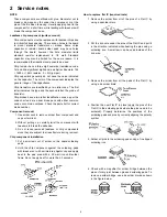


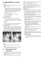
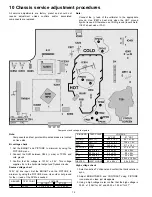


General guidelines
An isolation transformer should always be used during the
servicing of a receiver whose chassis is not isolated from
AC power line. Use a transformer of adequate power rating
as this protects the technician from accidents resulting in
personal injury from electrical shocks. It will also protect the
receiver from being damaged by accidental shorting that
may occur during servicing.
When servicing, observe the original lead dress, especially
in the high voltage circuit. Replace all damaged parts (also
parts that show signs of overheating.)
Always replace protective devices, such as fish paper,
isolation resistors and capacitors, and shields after
servicing
the
receiver.
Use
only
manufacturer’s
recommended rating for fuses, circuits breakers, etc.
High potentials are present when this receiver is operating.
Operation of the receiver without the rear cover introduces
danger for electrical shock. Servicing should not be
performed by anyone who is not thoroughly familiar with the
necessary precautions when servicing high voltage
equipment.
Extreme care should be practiced when handling the
picture tube. Rough handling may cause it to implode due
to atmospheric pressure. (14.7 lbs per sq. in.). Do not nick
or scratch the glass or subject it to any undue pressure.
When handling, use safety goggles and heavy gloves for
protection. Discharge the picture tube by shorting the anode
to chassis ground (not to the cabinet or to other mounting
hardware). When discharging connect cold ground (i.e. dag
ground lead) to the anode with a well insulated wire or use
a grounding probe.Avoid prolonged exposure at close
range to unshielded areas of the picture tube to prevent
exposure to x ray radiation.
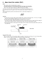
The test picture tube used for servicing the chassis at the
bench should incorporate safety glass and magnetic
shielding. The safety glass provide shielding for the tube
viewing area against x ray radiation as well as implosion.
The magnetic shield limits the x ray radiation around the
bell of the picture tube in addition to the restricting magnetic
effects. When using a picture tube test jig for service,
ensure that the jig is capable of handling 50kV without
causing x-ray radiation.
Before returning a serviced receiver to the owner, the
service technician must thoroughly test the unit to ensure
that is completely safe to operate. Do not use a line
isolation transformer when testing.
Leakage current cold check
Unplug the A.C. cord and connect a jumper between the
two plug prongs.Measure the resistance between the
jumpered AC plug and expose metallic parts such as
screwheads, antenna terminals, control shafts, etc. If the
exposed metallic part has a return path to the chassis, the
reading should be between 240k
Ω
and 5.2M
Ω
. If the
exposed metallic part does not have a return path to the
chassis, the reading should be infinite.
Leakage current hot check
Plug the AC cord directly into the AC outlet. Do not use an
isolation transformer during the check.
Connect a 1.5k
Ω
10 watt resistor in parallel with a 0.15µF
capacitor between an exposed metallic part and ground.
Use earth ground, for example a water pipe.
Using a DVM with a 1000 ohms/volt sensitivity or higher,
measure the AC potential across the resistor.
Repeat the procedure and measure the voltage present
with all other exposed metallic parts.
Verify that any potential does not exceed 0.75 volt RMS. A
leakage current tester (such a Simpson model 229,
Sencore model PR57 or equivalent) may be used in the
above procedure, in which case any current measure must
not exceed 0.5 milliamp. If any measurement is out of the
specified limits, there is a possibility of a shock hazard and
the receiver must be repaired and rechecked before it is
returned to the customer.
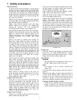
Hot check circuit
Insulation test
Connect an insulation tester between an exposed metallic
part and A.C. line. Apply 1080VAC/60Hz for 1 second.
Confirm that the current measurement is 0.5mA ~ 2.0mA.
Repeat test with other metallic exposed parts.
X-ray radiation
WARNING
The potential source of x-ray radiation in the TV set is in
the high voltage section and the picture tube.
NOTE
It is important to use an accurate, calibrated high
voltage meter.
Set the brightness, picture, sharpness and color controls to
minimum.
Measure the high voltage. The high voltage should be 30.55
± 1.25kV for 24” CRT and 29.25 ± 1.25kV for 27” CRT. If
the upper limit is out of tolerance, immediate service and
correction is required to insure safe operation and to
prevent the possibility of premature component failure.
Horizontal oscillator disable circuit test
This test must be performed as a final check before the
receiver is returned to the customer. See horizontal
oscillator disable circuit procedure check in this manual.
1 Safety precautions
3
Содержание CT-27SL14 - 27" CRT TV
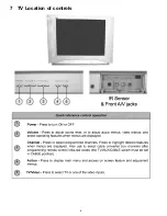
Страница 8: ...7 TV Location of controls 8 ...
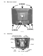
Страница 11: ...9 2 Back cover removal Back Cover 9 3 Inside View 11 ...
Страница 20: ...14 Reference for PDF colors 20 ...
Страница 21: ...15 Conductor views 21 ...
Страница 25: ...16 Block diagrams 25 ...
Страница 28: ...17 Schematics 28 ...
Страница 29: ...17 1 English schematic notes 29 ...
Страница 30: ...17 2 Notas de esquemáticos en español 30 ...
Страница 44: ...18 Parts location 44 ...
Страница 45: ...19 Parts list 19 1 Parts list notes 45 ...


