


- 28 -
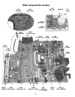
Service Adjustments (Electronic Controls, cont.)
White Balance
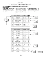
Service DACs. (C0) (C1) (C2) (C3) (C4) (C5)
Preparation:
1.
Turn the Receiver “ON” and allow 30 minutes
warm up at high brightness (White screen).
2.
Preset the following Service DACs:
• C0 . . . . . . . . . 0 255
• C1 . . . . . . . . . 0 255
• C2 . . . . . . . . . 0 255
• C3 . . . . . . . . . . . 80
• C4 . . . . . . . . . . . 80
• C5 . . . . . . . . . . . 80
3.
Confirm with Black-White pattern and a White
Screen the actual balance (Gray scale and white
level). If White Balance is required perform the
Procedure steps as follow.
Procedure:
CUT-OFF Adjustment (Low Lights)
1.
Apply a Black-White pattern.
2.
Connect a jumper from Q452-Base to cold
ground (
). (
Or apply +2.5 V dc to TP1 and cold
ground (
)
) to dis-habilitate the Neck Protector
circuit.
3.
Set Red Cut-Off (C0) and Blue Cut-Off (C2)
registers to 00.
4.
Press R-Tune in the remote control (to close the
vertical circuit and get green horizontal line),
5.
Connect scope probe between GK (C-Board) and
cold ground (
).
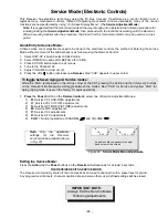
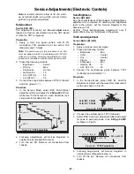
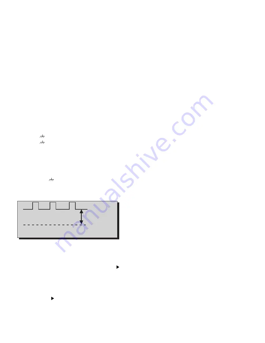
6.
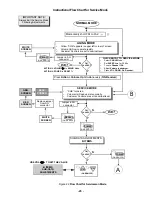
Measure waveform and adjust Register G-Cut Off,
C1, for the scanning period to be 175V, as shown
in Fig. 27
7.
Adjust Screen VR (at T551, Flyback) until the
green line just becomes visible.
8.
Press R-Tune in remote to open vertical.
9.
Select Red Cut-Off (C0) register, press R-Tune to
see green horizontal line. Increase C0 (volume )
until the line just become yellow (By mixing green
and red).
10. Press R-tune to open the vertical.
11. Select Blue Cut-Off (C2) register, press R-Tune to
close the vertical and see the yellow line, Increase
C2 (volume
) until line just becomes white
(mixing Green, Red and Blue).
12. Press R-Tune to open the vertical.
13. Confirm that a good gray scale is established by
viewing Black-White pattern.
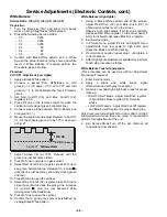
White Balance (High Lights)
1.
Using a Black-White pattern and White screen,
adjust Red Drive (C3) and Blue Drive (C5) to
obtain correct white level on the screen.
Observe High light areas, if white turns reddish,
decrease Red Drive register, on the other hand, if
white turns bluish, decrease Blue Drive register.
2.
Exit Service mode.
3.
In Picture menu, adjust Picture and Bright menu
adjustments from low scale to high scale and
check the Black and White tracking.
4.
If correction is needed repeat step 1 until obtain a
correct balance.
5.
After High lights adjustment is satisfactory, perform
Touch-Up procedure as follow.
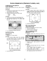
White Balance Touch-Up procedure
(This procedure can be used as a Minor Adjustment
Procedure if required)
1.
Enter Service mode
2.
Apply a Black and white image signal
(Recommended with gray tones also).
3.
Observe Low and High brightness areas for proper
tracking.
• HIGHT LIGHT areas - Adjust Red Drive register
(C3) and Blue Drive register (C5) for warm
whites.
• LOW LIGHT areas - Adjust Red Cut-Off register
and Blue Cut-Off register for proper black-gray.,
Since Low level adjustment has a minor effect on High
light adjustment levels than vice versa, is recommend
perform this adjustment at the end.
4.
Exit Service Mode.Turn off the set. Remove all
connections from chassis.
Figure 27. GK waveform
0V DC
(Ground)
175V DC
Содержание CT-20R6CE
Страница 55: ... 55 ...
Страница 56: ...Printed in USA K01032593CM0319 ...


