


- 15 -
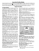
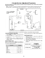
Chassis Service Adjustment Procedures
All service adjustments are factory preset and should not require adjustment unless controls and/or associated
components are replaced.
Note: Connect the (-) lead of the voltmeter to the appropriate ground. Use IC801’s heat sink when the HOT
ground symbol ( ) is used. Otherwise, use COLD ground (
) — Tuner shield, IC451’s heat sink or FA2.
COMPONENTS WITHIN DOT LINES ARE LOCATED AT THE OPOSITE SIDE OF BOARD.
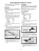
130.0V B+ Voltage Confirmation
1.
Set the Bright and the Picture to Minimum by using
the Picture Menu.
2.
Connect the DVM between C825(+ side) and cold
ground (
).
3.
Confirm that B+ voltage is 130.0V ± 2.5V. This
voltage supplies B+ to the Horizontal Output &
Flyback circuits.
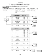
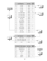
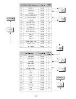
Source Voltage Chart
120V AC line input. Set the Bright and the Picture to
Minimum by using the Picture Menu. Use cold ground
(
) for the (-) lead of the DVM.
Adjust Picture Menu for normalized video adjustments.
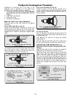
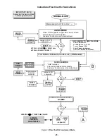
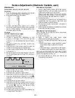
High Voltage Check
1.
Select an active TV channel and confirm that
horizontal is in sync.
2.
Adjust Brightness and Picture using Picture Icon
menu so video just disappears.
3.
Confirm B+ 130V is within limit.
4.
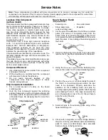
Using a high voltage meter confirm that the High
Voltage is:
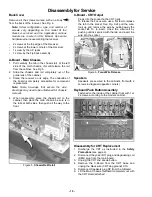
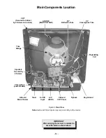
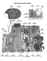
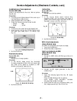
Figure 10. A-Board Main
Components and Test
Points
TPD8
SCREEN
FOCUS
IC552
IC551
T
U
N
E
R
COLD ( )
HOT ( )
F801
D554
IC451
A11
IC001
IC 801
C825
FA1
DATA
CLK
FA2
TPD9
D561
IC 003
IC 002
CRT
GND
IC2301
IC2302
IC050
TPD16
TPD15
TPD17
TPD14
TPE11
TPE10
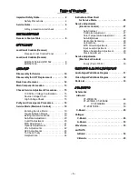
LOCATION
VOLTAGE
TPD8 26.0V
±
2V
TPD9 13.0V
±
2V
IC552 Pin3
5.0V ± 0.25V
IC551 Pin3
9.0V ± 0.25V
D554 Cathode
200V ± 15V
26.60kV±1.25kV
CT-20R6E/CE,
CT-20G6E/DE
(Models with Samsung CRT)
27.70kV±1.25kV
CT-2016SE, CT-2006SE,
CT-20D11E/DE
(Models with AMEC CRT)
Содержание CT-20R6CE
Страница 55: ... 55 ...
Страница 56: ...Printed in USA K01032593CM0319 ...


