background image

52 

13.  Protection Control 

13.1  Protection Control For All Operations 

13.1.1  Restart Control (Time Delay Safety Control) 

  The Compressor will not turn on within 3 minutes from the moment operation stops, although the unit is turned on 

again by pressing OFF/ON button at remote control within this period. 

  This control is not applicable if the power supply is cut off and on again. 

  This phenomenon is to balance the pressure inside the refrigerant cycle. 


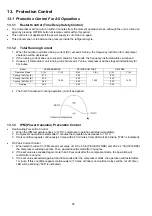
13.1.2  Total Running Current 

1  When the outdoor unit total running current (AC) exceeds X value, the frequency instructed for compressor 

operation will be decreased. 

2  If the running current does not exceed X value for 5 seconds, the frequency instructed will be increased. 
3  However, if total outdoor unit running current exceeds Y value, compressor will be stopped immediately for 

3 minutes.  


Model 

PE9RKE/UE9RKE 

PE12RKE/UE12RKE 

UE18RKE 

Operation Mode 

X (A) 

Y (A) 

X (A) 

Y (A) 

X (A) 

Y (A) 

Cooling / Soft Dry (A) 

4.73 

15.02 

6.82 

15.02 

8.76 

14.76 

Cooling / Soft Dry (B) 

4.25 

6.30 

8.25 

Cooling / Soft Dry (C) 

4.25 

6.30 

8.25 

Heating 

4.49 

6.00 

9.50 


4  The first 30 minutes of cooling operation, (A) will be applied. 


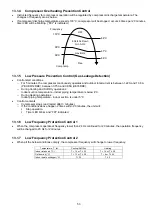
13.1.3  IPM (Power transistor) Prevention Control 

  Overheating Prevention Control 

1  When the IPM temperature rises to 120°C, compressor operation will stop immediately. 
2  Compressor operation restarts after 3 minutes the temperature decreases to 110°C. 
3  If this condition repeats continuously 4 times within 20 minutes, timer LED will be blinking (“F96” is indicated). 
 

  DC Peak Current Control 

1  When electric current to IPM exceeds set value of 16.0 ± 2.0A (PE,UE9/12RKE) and 20.2 ± 2.7A (UE18RKE), 

the compressor will stop operate. Then, operation will restart after 3 minutes. 

2  If the set value is exceeded again more than 30 seconds after the compressor starts, the operation will 

restart after 3 minute. 

3  If the set value exceeded again within 30 seconds after the compressor starts, the operation will restart after 

1 minute. If this condition repeats continuously for 7 times, all indoor and outdoor relays will be cut off, timer 
LED will be blinking (“F99” is indicated). 


Содержание CS-PE9RKE

Страница 1: ...lation or repairing of refrigerant circuit WARNING This service information is designed for experienced repair technicians only and is not designed for use by the general public It does not contain wa...

Страница 2: ...9 Quiet Operation Heating 51 12 10 Powerful Mode Operation 51 13 Protection Control 52 13 1 Protection Control For All Operations 52 13 2 Protection Control For Cooling Soft Dry Operation 54 13 3 Prot...

Страница 3: ...Otherwise it may cause electrical shock and fire in case equipment breakdown or insulation breakdown 10 Do not use joint cable for indoor outdoor connection cable Use the specified Indoor Outdoor con...

Страница 4: ...g point is 50 F 70 F 30 C 40 C higher Please use a high temperature solder iron In case of the soldering iron with temperature control please set it to 700 20 F 370 10 C Pb free solder will tend to sp...

Страница 5: ...41 26 22 42 30 22 Power Level dB 57 42 38 58 46 38 Outdoor Noise dB A 47 48 Power Level dB 62 63 Heating Capacity kW 0 80 3 30 4 10 0 80 4 00 5 10 BTU h 2730 11300 14000 2730 13600 17400 kcal h 690 2...

Страница 6: ...h Pt h 1 5 3 2 2 0 4 2 Indoor Airflow QLo Cool m3 min ft3 min 5 26 186 5 85 207 Heat m3 min ft3 min 6 80 240 7 51 265 Lo Cool m3 min ft3 min 6 68 236 8 10 286 Heat m3 min ft3 min 7 62 269 9 98 352 Me...

Страница 7: ...m C 24 18 24 18 Minimum C 10 11 10 11 1 Cooling capacities are based on indoor temperature of 27 C Dry Bulb 80 6 F Dry Bulb 19 0 C Wet Bulb 66 2 F Wet Bulb and outdoor air temperature of 35 C Dry Bulb...

Страница 8: ...42 30 22 Power Level dB 57 42 38 58 46 38 Outdoor Noise dB A 47 48 Power Level dB 62 63 Heating Capacity kW 0 80 3 30 4 10 0 80 4 00 5 10 BTU h 2730 11300 14000 2730 13600 17400 kcal h 690 2840 3530...

Страница 9: ...2 2 0 4 2 Indoor Airflow QLo Cool m3 min ft3 min 5 26 186 5 85 207 Heat m3 min ft3 min 6 80 240 7 51 265 Lo Cool m3 min ft3 min 6 68 236 8 10 286 Heat m3 min ft3 min 7 62 269 9 98 352 Me Cool m3 min...

Страница 10: ...um C 24 18 24 18 Minimum C 10 11 10 11 1 Cooling capacities are based on indoor temperature of 27 C Dry Bulb 80 6 F Dry Bulb 19 0 C Wet Bulb 66 2 F Wet Bulb and outdoor air temperature of 35 C Dry Bul...

Страница 11: ...A H L Q Lo 44 37 34 Power Level dB 60 53 50 Outdoor Noise dB A 48 Power Level dB 63 Heating Capacity kW 0 98 5 40 7 70 BTU h 3340 18400 26300 kcal h 840 4640 6620 Running Current A 6 70 Input Power W...

Страница 12: ...ure Removal L h Pt h 2 8 5 9 Indoor Airflow QLo Cool m3 min ft3 min 11 37 402 Heat m3 min ft3 min 13 05 461 Lo Cool m3 min ft3 min 12 59 445 Heat m3 min ft3 min 14 28 504 Me Cool m3 min ft3 min 14 43...

Страница 13: ...F Wet Bulb and outdoor air temperature of 35 C Dry Bulb 95 F Dry Bulb 24 C Wet Bulb 75 2 F Wet Bulb 2 Heating capacities are based on indoor temperature of 20 C Dry Bulb 68 F Dry Bulb and outdoor air...

Страница 14: ...CU UE9 12 18RKE long piping up to 15 meters Easy to use remote control Quality Improvement o Random auto restart after power failure for safety restart operation o Gas leakage protection o Prevent com...

Страница 15: ...UIET Orange POWERFUL Orange POWER TIMER POWERFUL QUIET 4 2 Outdoor Unit 4 3 Remote Control MODE TEMP OFF ON TIMER SET CANCEL ON OFF 1 2 3 FAN SPEED SET CHECK CLOCK RESET AC RC AUTO HEAT COOL DRY AIR S...

Страница 16: ...Left piping hole Remote Control Remote Control Holder 22 47 134 61 51 870 1 2 1 2 214 61 45 Right piping hole 290 214 125 115 60 60 410 41 61 Gas side Liquid side Relative position between the indoor...

Страница 17: ...0 290 240 Right piping hole 1 2 1070 1 2 115 60 125 60 41 61 410 Relative position between the indoor unit and the installation plate Front View 264 3 Unit mm Right piping hole Left piping hole Instal...

Страница 18: ...w Front View Side View Side View Anchor Bolt Pitch 320 570 Space necessary for installation 100 mm 100 mm 1000 mm Unit mm 3 way valve at Gas side Low Pressure 2 way valve at Liquid side High Pressure...

Страница 19: ...e View Side View Anchor Bolt Pitch 330 540 Space necessary for installation 100mm 100mm 1000mm Unit mm 3 way valve at Gas side Low Pressure 2 way valve at Liquid side High Pressure 22 124 62 6 330 619...

Страница 20: ...P SENSOR PIPE TEMP SENSOR PIPE TEMP SENSOR LIQUID SIDE UE18RK UE PE9 12RK 2 WAY VALVE 3 WAY VALVE GAS SIDE COOLING HEAT EXCHANGER EVAPORATOR HEATING COMPRESSOR 4 WAYS VALVE HEAT EXCHANGER CONDENSER MU...

Страница 21: ...U UE9RKE CS UE12RKE CU UE12RKE 1 FUSE101 FUSE104 REACTOR FUSE102 RY PWR PTC1 PTC NTC TH3 CT102 4 WAYS VALVE RY AC FUSE103 IC19 MS 3 MS 3 RY PWR RY PWR2 FUSE301 TEMP FUSE TEMP FUSE SC L U M INDOOR UNIT...

Страница 22: ...103 RY PWR NTC TH1 CT101 C103 4 WAYS VALVE FUSE101 IC19 MS 3 MS 3 RY PWR RY PWR2 FUSE301 TEMP FUSE TEMP FUSE SC L U M INDOOR UNIT OUTDOOR UNIT SC 2 3 N SINGLE PHASE POWER SUPPLY 1 230V 50Hz NOISE FILT...

Страница 23: ...NG TERMINAL L N SINGLE PHASE POWER SUPPLY 1 230V 50Hz ELECTRONIC CONTROLLER MAIN UP DOWN LOUVER MOTOR CN STM1 WHT BR 1 5 1 5 R O M Y P REMARKS B BLUE P PINK BR BROWN O ORANGE BL BLACK Y YELLOW W WHITE...

Страница 24: ...ONTROLLER MAIN LEFT RIGHT LOUVER MOTOR CN STM2 YLW BR 1 5 1 5 R O M Y P UP DOWN LOUVER MOTOR CN STM1 WHT BR 1 5 1 5 R O M Y P REMARKS B BLUE P PINK BR BROWN O ORANGE BL BLACK Y YELLOW W WHITE G GREEN...

Страница 25: ...WITCHING POWER SUPPLY CIRCUIT FUSE102 T3 15A L250V FUSE101 20A 250V 3 2 1 COMMUNICATION CIRCUIT PFC CIRCUIT W U V FAN MOTOR ELECTRONIC CONTROLLER MS 3 FUSE104 15A 250V NOISE FILTER CIRCUIT RECTIFICATI...

Страница 26: ...LVE 1 3 CN HOT WHT CN TH1 WHT P N SWITCHING POWER SUPPLY CIRCUIT FUSE103 20A 250V 3 2 1 COMMUNICATION CIRCUIT PFC CIRCUIT W U V FAN MOTOR ELECTRONIC CONTROLLER MS 3 NOISE FILTER CIRCUIT RECTIFICATION...

Страница 27: ...7 R89 CN RMT 9 8 11 10 1 5V C3 0 1 16V ELECTRONIC CONTROLLER MAIN SW01 4 1 FAN MOTOR CN FM WHT Y 7 4 1 B W BL R M FUSE301 T3 15A L250V RY PWR RY PWR2 Y G Y G TEMP FUSE 102 C 3A TEMP FUSE 102 C 3A EVA...

Страница 28: ...7 4 1 B W BL R M FUSE301 T3 15A L250V RY PWR RY PWR2 Y G Y G TEMP FUSE 102 C 3A TEMP FUSE 102 C 3A EVAPORATOR 1 2 3 AC303 WHT AC304 RED G301 GRN GROUNDING TERMINAL L R W G P BL BR TERMINAL BOARD GROUN...

Страница 29: ...RY GRY RAT1 GRY REACTOR RED BLU YLW U RED FUSE103 T3 15A L250V V BLU W YLW U V W 3 5 1 10 14 16 P N SWITCHING POWER SUPPLY CIRCUIT FUSE102 T3 15A L250V FUSE101 20A 250V 3 2 1 COMMUNICATION CIRCUIT PFC...

Страница 30: ...SENSOR 50k 3950 1 3 t 0 P N FUSE103 20A 250V 3 2 1 PFC CIRCUIT W U V FAN MOTOR ELECTRONIC CONTROLLER MS 3 NOISE FILTER CIRCUIT RECTIFICATION CIRCUIT EXPANSION VALVE 1 2 3 4 5 6 M MS 3 FUSE104 T3 15A...

Страница 31: ...31 10 Printed Circuit Board 10 1 Indoor Unit 10 1 1 Main Printed Circuit Board CN FM CN STM1 CN STM2 UE18RKE only CN TH CN DISP CN RMT RY PWR AC303 G301 AC304 JP1 Random Auto Restart enable disable...

Страница 32: ...32 10 1 2 Indicator Receiver Printed Circuit Board CN DISP...

Страница 33: ...2 Outdoor Unit 10 2 1 Main Printed Circuit Board 10 2 1 1 CU PE9RKE CU PE12RKE CU UE9RKE CU UE12RKE CN HOT CN STM CN TH CN MTR1 CN MTR2 CN TANK AC BLK DATA AC WHT POWER TRANSISTOR IPM CURRENT TRANSFOR...

Страница 34: ...34 10 2 1 2 CU UE18RKE CN HOT CN STM CN TH1 CN MTR2 CN MTR1 CN TANK AC BLK FG1 DATA FG2 AC WHT RAT1 RAT2 POWER TRANSISTOR IPM CURRENT TRANSFORMER CT...

Страница 35: ...35 10 2 2 CPU Printed Circuit Board 10 2 2 1 CU PE9RKE CU PE12RKE CU UE9RKE CU UE12RKE...

Страница 36: ...gas m Gas Liquid UE9 PE9 1 0HP 9 52mm 3 8 6 35mm 1 4 5 15 3 15 20 7 5 UE12 PE12 5 7 0 2 5 1 3 5 1 P H 5 1 UE18 2 0HP 12 7mm 1 2 15 3 15 20 7 5 Example For UE9 If the unit is installed at 10 m distanc...

Страница 37: ...he unit on the concrete wall consider using anchor bolts o Always mount the installation plate horizontally by aligning the marking off line with the thread and using a level gauge 2 Drill the piping...

Страница 38: ...necting the piping column in outdoor unit section Below steps are done after connecting the outdoor piping and gas leakage confirmation Step 7 Insulate and finish the piping Step 8 Secure the Indoor U...

Страница 39: ...to the power supply through Isolating Devices Disconnecting means o Connect approved type polychloroprene sheathed power supply cord 3 1 5 mm2 1 0 1 75HP 3 2 5 mm2 2 0 2 5HP type designation 60245 IE...

Страница 40: ...ew and close the front panel Recommended length mm Tape Connection cable Tape Power supply cord Recommended length mm a 55 b 35 c 35 d 50 e 40 f 35 g 60 Terminal Board Control Board Earth wire longer...

Страница 41: ...NG REQUIREMENT Conductor fully inserted Conductor not fully inserted gap between wires WARNING RISK OF FIRE JOINING OF WIRES MAY CAUSE OVERHEATING AND FIRE Do not joint wires OR OR OR Use complete wir...

Страница 42: ...ssembly onto the copper pipe In case of using long piping Connect the piping Align the center of piping and sufficiently tighten the flare nut with fingers Further tighten the flare nut with torque wr...

Страница 43: ...e that the needle in the gauge does not move after approximately five minutes Note BE SURE TO TAKE THIS PROCEDURE IN ORDER TO AVOID REFRIGERENT GAS LEAKAGE 5 Disconnect the charging hose from the vacu...

Страница 44: ...erly earthed Earth wire shall be Yellow Green Y G in colour and longer than other AC wires for safety reason 11 3 5 Piping Insulation 1 Please carry out insulation at pipe connection portion as mentio...

Страница 45: ...ting temperature and it is updated continuously whenever the electrical power is supplied to the unit 12 1 2 Cooling Operation 12 1 2 1 Thermostat control Compressor is OFF when Intake Air Temperature...

Страница 46: ...ent onwards o If indoor intake temperature remote control setting temperature 3 C if previous operate in DRY mode then continue in DRY mode otherwise COOL mode is decided o If 2 C indoor intake temper...

Страница 47: ...550 rpm or 50 rpm continue for 10 seconds then fan motor error counter increase fan motor is then stop and restart If the fan motor counter becomes 7 times then H19 fan motor error is detected Operati...

Страница 48: ...5 35 Control with dew 5 35 Manual Usual 5 12 5 20 27 5 35 Control with dew 5 12 5 20 27 5 35 Heating Manual Usual 5 17 5 30 42 5 55 CS UE18RKE 1 Automatic vertical airflow direction can be set using...

Страница 49: ...Control There are 2 sets of ON and OFF timer available to turn the unit ON or OFF at different preset time If more than one timer had been set the upcoming timer will be displayed and will activate i...

Страница 50: ...ccurs 12 8 Quiet Operation Cooling Mode Cooling Area of Dry Mode A Purpose To provide quiet cooling operation compare to normal operation B Control condition a Quiet operation start condition o When P...

Страница 51: ...on of the new fan speed 4 When operation mode is changed quiet operation is shifted to quiet operation of the new mode 5 During quiet operation if timer on activates quiet operation maintains 6 After...

Страница 52: ...4 73 15 02 6 82 15 02 8 76 14 76 Cooling Soft Dry B 4 25 6 30 8 25 Cooling Soft Dry C 4 25 6 30 8 25 Heating 4 49 6 00 9 50 4 The first 30 minutes of cooling operation A will be applied 13 1 3 IPM Pow...

Страница 53: ...8RKE o During Cooling and Soft Dry operations Indoor suction temperature indoor piping temperature is below 4 C o During Heating operations Indoor piping temperature indoor suction is under 5 C Contro...

Страница 54: ...anger is higher than 5 C At the same time indoor fan speed will be higher than during its normal operation If indoor heat exchanger temperature is higher than 5 C for 5 minutes the fan speed will retu...

Страница 55: ...at minimum airflow for 20 seconds 13 3 Protection Control For Heating Operation 13 3 1 Intake Air Temperature Control Compressor will operate at limited freq if indoor intake air temperature is 30 C...

Страница 56: ...y will be regulated up to 600 seconds 13 3 5 Cold Draught Prevention Control When indoor pipe temperature is low cold draught operation starts where indoor fan speed will be reduced 13 3 6 Deice Opera...

Страница 57: ...3 REMOTE CONTROL NUMBER SWITCH MODE The Remote Control Number Switch Mode will be activated if the Auto OFF ON button is pressed continuously for more than 11 seconds 3 beep sounds will occur at 11th...

Страница 58: ...ote Control Receiving Sound OFF ON Mode is restarted 14 2 Remote Control Button 14 2 1 SET Button To check remote control transmission code and store the transmission code to EEPROM o Press Set button...

Страница 59: ...problems before inspecting the refrigeration cycle Such problems include insufficient insulation problem with the power source malfunction of a compressor and a fan The normal outlet air temperature a...

Страница 60: ...lectric current during operation Low Pressure High Pressure Electric current during operation Insufficient refrigerant gas leakage Clogged capillary tube or Strainer Short circuit in the indoor unit H...

Страница 61: ...wer on 2 Press the CHECK button on the remote controller continuously for 5 seconds 3 will be displayed on the remote controller display Note Display only for No transmitting signal no receiving sound...

Страница 62: ...lity Port is ON for 10s during ion device off ion device PCB H27 Outdoor air temperature sensor abnormality Continuous for 5s Outdoor air temperature sensor open or short circuit Outdoor air temperatu...

Страница 63: ...ing abnormality 3 times happen within 40 minutes Wrong wiring and connecting pipe expansion valve leakage indoor heat exchanger sensor open circuit Check indoor outdoor connection wire and pipe Indoor...

Страница 64: ...ved from outdoor unit in indoor unit signal transmission is checked whether it is normal Malfunction Caused Faulty indoor unit PCB Faulty outdoor unit PCB Indoor unit outdoor unit signal transmission...

Страница 65: ...re interconnected Malfunction Caused Wrong models interconnected Wrong indoor unit or outdoor unit PCBs mounted Indoor unit or outdoor unit PCBs defective Indoor outdoor unit signal transmission error...

Страница 66: ...tion Decision Conditions During startup and operation of cooling and heating the temperatures detected by the indoor intake air temperature sensor are used to determine sensor errors Malfunction Cause...

Страница 67: ...Decision Conditions During startup and operation of cooling and heating the temperatures detected by the outdoor compressor temperature sensor are used to determine sensor errors Malfunction Caused F...

Страница 68: ...on Conditions An input current detected by Current Transformer CT is below threshold value when the compressor is operating at certain frequency value for 3 minutes Malfunction Caused Lack of gas Brok...

Страница 69: ...termine abnormal fan motor feedback of rotation 2550rpm or 50rpm Malfunction Caused Operation stops due to short circuit inside the fan motor winding Operation stops due to breaking of wire inside the...

Страница 70: ...Decision Conditions During startup and operation of cooling and heating the temperatures detected by the indoor heat exchanger temperature sensor are used to determine sensor errors Malfunction Caused...

Страница 71: ...tion Decision Conditions During startup and operation of cooling and heating the temperatures detected by the outdoor air temperature sensor are used to determine sensor errors Malfunction Caused Faul...

Страница 72: ...tion Decision Conditions During startup and operation of cooling and heating the temperatures detected by the outdoor pipe temperature sensor are used to determine sensor errors Malfunction Caused Fau...

Страница 73: ...ion Decision Conditions During startup and operation of cooling and heating the temperatures detected by the outdoor discharge pipe temperature sensor are used to determine sensor errors Malfunction C...

Страница 74: ...ction Decision Conditions During startup and operation of cooling and heating the temperatures detected by the outdoor heat exchanger temperature sensor are used to determine sensor errors Malfunction...

Страница 75: ...lfunction Decision Conditions The supply power is detected for its requirement by the indoor outdoor transmission Malfunction Caused Wrong models interconnected Wrong indoor unit and outdoor unit PCBs...

Страница 76: ...tion Decision Conditions During startup and operation of cooling and heating the temperatures detected by the outdoor heat sink temperature sensor are used to determine sensor errors Malfunction Cause...

Страница 77: ...ecision Conditions During startup and operation of cooling and heating the temperatures detected by the outdoor gas pipe temperature sensor are used to determine sensor errors Malfunction Caused Fault...

Страница 78: ...tion Decision Conditions During startup and operation of cooling and heating the temperatures detected by the outdoor liquid pipe temperature sensor are used to determine sensor errors Malfunction Cau...

Страница 79: ...NO When abnormality indication starts again Turn off power supply and disconnect CN MTR2 connector Connect inverter checker to CN MTR2 then turn power on Replace fan motor For safety reason and to pre...

Страница 80: ...pressure is detected when indoor heat exchanger is detecting very high temperature when the unit is operating in heating operation Phenomena unit is stopping and re starting very often in heating mod...

Страница 81: ...takes place when indoor pipe temperature is lower than 2 C Malfunction Caused Air short circuit at indoor unit Clogged indoor unit air filter Dust accumulation on the indoor unit heat exchanger 2 3 w...

Страница 82: ...old during heating except deice or when indoor heat exchanger is hot during cooling and compressor operating the 4 way valve is detected as malfunction Malfunction Caused Indoor heat exchanger pipe th...

Страница 83: ...ature and indoor pipe temperature is above 10 C or indoor pipe temperature is below 1 0 C Remark When the indoor standby unit is freezing the outdoor unit transfers F17 error code to the corresponding...

Страница 84: ...tartup and operation of cooling and heating when Power Factor Correction PFC protection circuitry at the outdoor unit main PCB senses abnormal DC voltage level for power transistors When DC voltage de...

Страница 85: ...igeration Cycle Abnormality Malfunction Decision Conditions The input current is low while the compressor is running at higher than the setting frequency Malfunction Caused Lack of gas 3 way valve clo...

Страница 86: ...on Decision Conditions A compressor rotation failure is detected by checking the compressor running condition through the position detection circuit Malfunction Caused Compressor terminal disconnect F...

Страница 87: ...the outdoor unit heat exchanger thermistor Malfunction Caused Outdoor heat exchanger temperature rise due to short circuit of hot discharge air flow Outdoor heat exchanger temperature rise due to defe...

Страница 88: ...ated o Heat Sink Overheating During operation of cooling and heating when heat sink temperature data 90 C is detected by the heat sink temperature sensor Malfunction Caused IPM overheats due to short...

Страница 89: ...ing and heating when compressor tank temperature data 112 C is detected by the compressor tank temperature sensor Malfunction Caused Faulty compressor tank temperature sensor 2 3 way valve closed Refr...

Страница 90: ...n of cooling and heating when an input over current X value in Total Running Current Control is detected by checking the input current value being detected by current transformer CT with the compresso...

Страница 91: ...ating when inverter DC peak data is received by the outdoor internal DC Peak sensing circuitry Malfunction Caused DC current peak due to compressor failure DC current peak due to defective power trans...

Страница 92: ...result in electric shocks 16 1 Indoor Electronic Controllers Cross Flow Fan and Indoor Fan Motor Removal Procedures 16 1 1 CS PE9RKE CS PE12RKE CS UE9RKE CS UE12RKE 16 1 1 1 To remove front grille 2...

Страница 93: ...M CN STM1 CN TH CN DISP CN RMT RY PWR AC303 G301 AC304 RY PWR2 Figure 3 Figure 4 16 1 1 4 To remove discharge grille 10 Pull out to remove the drain hose from the discharge grille 11 Then pull the dis...

Страница 94: ...2 Remove 4 screws holding the control board then pull out the control board Figure 6 16 1 1 6 To remove cross flow fan and indoor fan motor 13 Remove the screw that holding the cross flow fan and fan...

Страница 95: ...fan Reminder To reinstall the fan motor adjust the fan motor connector to 45 towards you before fixing control board 17 Remove the cross flow fan from the unit by pulling it to the left and downward E...

Страница 96: ...s discharged sufficiently before proceeding with repair work Failure to heed this caution may result in electric shocks 16 2 Indoor Electronic Controllers Cross Flow Fan and Indoor Fan Motor Removal P...

Страница 97: ...97 16 2 1 3 To remove power electronic controller CN FM CN STM1 CN TH CN DISP CN RMT RY PWR AC303 G301 AC304 RY PWR2 Figure 3 Figure 4 16 2 1 4 To remove discharge grille Figure 5...

Страница 98: ...98 16 2 1 5 To remove control board Figure 6 16 2 1 6 To remove cross flow fan and indoor fan motor Figure 7 Figure 8...

Страница 99: ...99 Figure 9 Figure 10...

Страница 100: ...nel Fig 1 2 Remove the 6 screws of the Front Panel Fig 2 3 Remove the screw of the Terminal Board Cover 4 Remove the Top Cover of the Control Board by 4 hooks Fig 3 5 Remove the Control Board as follo...

Страница 101: ...electrostatic discharge 1 Remove the 5 screws of the Top Panel Fig 1 2 Remove the 8 screws of the Front Panel Fig 2 3 Remove the screw of the Terminal Board Cover 4 Remove the Top Cover of the Control...

Страница 102: ...C IP TC SHC IP TC SHC IP 27 19 0 3612 3056 827 3878 3074 615 3642 3010 827 3500 3067 1090 22 0 4082 2274 670 4005 2197 612 3974 2114 791 3503 2002 1071 23 15 7 3643 3607 736 3439 3405 689 3299 3266 84...

Страница 103: ...RKE CU PE12RKE CS UE12RKE CU UE12RKE Indoor C Outdoor WB C DB 10 7 2 7 12 TC IP TC IP TC IP TC IP TC IP 24 2278 1358 2993 1415 3381 1325 3775 1109 4099 1142 20 2400 1340 3200 1410 3700 1300 4000 1100...

Страница 104: ...length forced cooling at 16 C Hi fan Compressor frequency Rated for cooling operation Piping length 5m Voltage 230V 18 1 1 CS CU PE9RKE CS CU UE9RKE Outlet Air C Outlet Air C Outdoor Air Temperature C...

Страница 105: ...ure MPa Outdoor Air Temperature C Current A Outdoor Air Temperature C 12 1 50 2 00 2 50 3 00 3 50 4 00 5 00 4 50 6 00 5 50 12 16 20 24 28 32 36 40 44 48 0 60 0 70 0 80 0 90 1 10 1 00 16 20 24 28 32 36...

Страница 106: ...ow Pressure MPa 10 0 11 0 12 0 13 0 14 0 15 0 16 0 17 0 18 0 3 5 7 9 11 13 15 17 19 21 23 25 27 29 31 33 35 37 39 41 43 45 0 80 0 90 1 00 1 10 1 20 1 30 1 40 1 50 3 5 7 9 11 13 15 17 19 21 23 25 27 29...

Страница 107: ...frequency Rated for Heating operation Piping length 5m Voltage 230V 18 2 1 CS CU PE9RKE CS CU UE9RKE Outlet Air C Outlet Air C Outdoor Air Temperature C High Pressure MPa Outdoor Air Temperature C Cur...

Страница 108: ...et Air C Outdoor Air Temperature C High Pressure MPa Outdoor Air Temperature C Current A Outdoor Air Temperature C 3 80 4 30 5 30 6 30 4 80 5 80 6 80 1 60 1 80 2 00 2 20 2 40 2 60 2 80 3 00 3 60 3 40...

Страница 109: ...re C High Pressure MPa 3 00 4 00 5 00 6 00 7 00 8 00 9 00 10 00 16 14 12 10 8 6 4 2 0 2 4 6 8 10 12 14 16 18 20 22 24 26 25 00 30 00 35 00 40 00 45 00 50 00 55 00 16 14 12 10 8 6 4 2 0 2 4 6 8 10 12 1...

Страница 110: ...CS CU UE12RKE Cooling Capacity Correction Factor Cooling Capacity Correction Factor Heating Capacity Correction Factor Pipe Length m Pipe Length m 0 92 0 94 0 96 0 98 1 00 1 02 2 3 4 5 6 7 8 9 10 11...

Страница 111: ...Factor Heating Capacity Correction Factor Pipe Length m Pipe Length m 0 95 0 97 0 99 1 01 1 03 2 3 4 5 6 7 8 9 10 11 12 13 14 15 16 0 95 0 96 0 97 0 98 0 99 1 00 1 01 2 3 4 5 6 7 8 9 10 11 12 13 14 1...

Страница 112: ...I I I I I I I I I I O I 46 47 48 54 55 56 I I I I I I I I O I 62 57 58 59 60 40 3 4 2 5 1 27 23 11 16 26 34 28 29 30 39 9 37 35 7 38 8 41 42 43 50 53 52 51 44 10 12A 49 CWH55025J CWH55051J Note The a...

Страница 113: ...ULCRUM 1 CWH621131 29 VERTICAL VANE 8 CWE241374 30 CONNECTING BAR 2 CWE261251 33 AIR SWING MOTOR 1 CWA981264 O 34 CAP DRAIN TRAY 1 CWH521259 35 HORIZONTAL VANE COMPLETE 1 CWE24C1385 36 REMOTE CONTROL...

Страница 114: ...TION QTY CS PE9RKE CS PE12RKE REMARK 60 INSTALLATION INSTRUCTION 1 CWF616728 62 OPERATING INSTRUCTION 1 CWF569883 NOTE All parts are supplied from PAPAMY Malaysia Vendor Code 00029488 O marked parts a...

Страница 115: ...ULCRUM 1 CWH621131 29 VERTICAL VANE 8 CWE241374 30 CONNECTING BAR 2 CWE261251 33 AIR SWING MOTOR 1 CWA981264 O 34 CAP DRAIN TRAY 1 CWH521259 35 HORIZONTAL VANE COMPLETE 1 CWE24C1385 36 REMOTE CONTROL...

Страница 116: ...S UE12RKE REMARK 59 INSTALLATION INSTRUCTION 1 CWF616727 60 INSTALLATION INSTRUCTION 1 CWF616728 62 OPERATING INSTRUCTION 1 CWF569883 NOTE All parts are supplied from PAPAMY Malaysia Vendor Code 00029...

Страница 117: ...I 56 I I 60 I I 59 2 5 40 45 44 1 27 13 23 11 16 24 24a 15 12 25 33 26 34 28 28 29 30 31 32 35 42 41 37 38 39 7 53 52 51 50 36 CWH55025 J CWH55051 J 62 Note The above exploded view is for the purpose...

Страница 118: ...CWD933031 28 FULCRUM 2 CWH621138 29 VERTICAL VANE 11 CWE241374 30 CONNECTING BAR 1 CWE261257 31 CONNECTING BAR 1 CWE261258 32 AIR SWING MOTOR 1 CWA98K1018 O 33 AIR SWING MOTOR 1 CWA981241 O 34 CAP DR...

Страница 119: ...CWF616725 58 INSTALLATION INSTRUCTION 1 CWF616726 59 INSTALLATION INSTRUCTION 1 CWF616727 60 INSTALLATION INSTRUCTION 1 CWF616728 62 AIR PURIFYING FILTER 1 CWD00C1291 O NOTE All parts are supplied fr...

Страница 120: ...5 3 6 5 8 7 27 28 32 30 17 16 10 11 4 12 22 21 19 26 25 38 39 9 2 1 23A 23B 31 35 33 20 14 24 29 55 53 54 51 52 23C 43 42 50 13 Note The above exploded view is for the purpose of parts disassembly and...

Страница 121: ...OF MATERIAL 1 CWG302948 23B SOUND PROOF MATERIAL 1 CWG302316 23C SOUND PROOF MATERIAL 1 CWG302317 24 SENSOR CO COMP TEMP 1 CWA50C2632 O 25 CONTROL BOARD COVER TOP 1 CWH131264 26 ELECTRONIC CONTROLLER...

Страница 122: ...OF MATERIAL 1 CWG302948 23B SOUND PROOF MATERIAL 1 CWG302316 23C SOUND PROOF MATERIAL 1 CWG302317 24 SENSOR CO COMP TEMP 1 CWA50C2632 O 25 CONTROL BOARD COVER TOP 1 CWH131264 26 ELECTRONIC CONTROLLER...

Страница 123: ...1 20 9 31 11 10 15 1 16 17 4 23A 23B 23C 22 2 3 8 7 5 30 12 24 29 41 13 6 47 46 48 49 50 25 45 14 42 43 Note The above exploded view is for the purpose of parts disassembly and replacement The non num...

Страница 124: ...PROOF MATERIAL 1 CWG302952 23C SOUND PROOF MATERIAL 1 CWG302740 24 SENSOR COMPLETE COMP TEMP 1 CWA50C2894 O 25 CONTROL BOARD COVER TOP 1 CWH131473 26 ELECTRONIC CONTROLLER MAIN 1 CWA73C9003R O 27 TERM...

Страница 125: ...125 PAPAMY Printed in Malaysia SY0115 0...

Отзывы: