


47
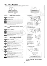
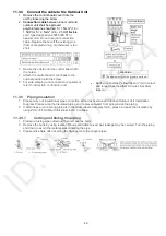
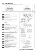
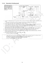
12.2.4 Connect the Cable to the Indoor Unit
1. The inside and outside connection cable can
be connected without removing the front grille.
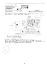
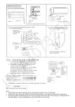
2.
Connection cable
between indoor unit and
outdoor unit shall be approved
polychloroprene sheathed 6 × 1.5 mm
2
flexible
cord, type designation 60245 IEC 57 or
heavier cord. Do not use joint connection cable.
Replace the wire if the existing wire (from
concealed wiring, or otherwise) is too short.
•
Secure the connection cable onto the control board with the holder.
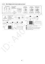
WARNING
This equipment must be properly earthed.
Note:
•
Isolating Devices (Disconnecting means) should have minimum 3.0 mm contact gap.
•
Ensure the colour of wires of outdoor unit and the terminal Nos. are the same to the indoor’s respectively.
•
Earth wire shall be Yellow/Green (Y/G) in colour and longer than other AC wires as shown in the figure for the
electrical safety in case of the slipping out of the cord from the anchorage.
Содержание CS-A12PKD
Страница 12: ...12 4 Location of Controls and Components 4 1 Indoor Unit 4 2 Outdoor Unit 4 3 Remote Control...
Страница 13: ...13 5 Dimensions 5 1 Indoor Unit 5 1 1 CS A9PKD CS A12PKD...
Страница 14: ...14 5 1 2 CS A18PKD CS A24PKD CS A28PKD...
Страница 15: ...15 5 2 Outdoor Unit 5 2 1 CU A9PKD 5 2 2 CU A12PKD...
Страница 16: ...16 5 2 3 CU A18PKD...
Страница 17: ...17 5 2 4 CU A24PKD CU A28PKD...
Страница 18: ...18 6 Refrigeration Cycle Diagram 6 1 CS A9PKD CU A9PKD CS A12PKD CU A12PKD...
Страница 19: ...19 6 2 CS A18PKD CU A18PKD CS A24PKD CU A24PKD CS A28PKD CU A28PKD...
Страница 20: ...20 7 Block Diagram 7 1 CS A9PKD CU A9PKD...
Страница 21: ...21 7 2 CS A12PKD CU A12PKD...
Страница 22: ...22 7 3 CS A18PKD CU A18PKD CS A24PKD CU A24PKD...
Страница 23: ...23 7 4 CS A28PKD CU A28PKD...
Страница 28: ...28 9 Electronic Circuit Diagram 9 1 CS A9PKD CU A9PKD...
Страница 29: ...29 9 2 CS A12PKD CU A12PKD...
Страница 30: ...30 9 3 CS A18PKD CU A18PKD CS A24PKD CU A24PKD...
Страница 31: ...31 9 4 CS A28PKD CU A28PKD...
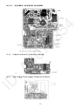
Страница 32: ...32 10 Printed Circuit Board 10 1 Indoor Unit 10 1 1 Main Printed Circuit Board 10 1 1 1 CS A9PKD CS A12PKD...
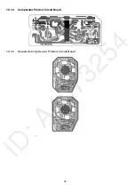
Страница 34: ...34 10 1 4 Comparator Printed Circuit Board 10 1 5 Human Activity Sensor Printed Circuit Board...
Страница 40: ...40 11 2 5 Wire Stripping And Connecting Requirement...
Страница 48: ...48 12 2 5 Wire Stripping And Connecting Requirement...
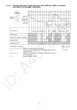
Страница 55: ...55 13 2 2 Cooling Operation Time Diagram For CS A18PK CU A18PK CS A24PK CU A24PK and CS A28PK CU A28PK...
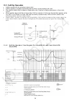
Страница 57: ...57 13 3 2 Soft Dry Operation Time Diagram For CS A18PK CU A18PK CS A24PK CU A24PK and CS A28PK CU A28PK...
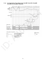
Страница 87: ...87 Normal Deice Time Diagram Overload Deice Time Diagram...
Страница 92: ...92 a Normal Deice Time Diagram b Overload Deice Time Diagram...
Страница 98: ...98 Figure 3 Figure 4 17 1 1 3 To remove discharge grille Figure 5...
Страница 100: ...100 Figure 9 Figure 10...
Страница 102: ...102 17 2 1 3 To remove electronic controller Figure 13 Figure 14 Figure 15 17 2 1 4 To remove discharge grille Figure 16...
Страница 104: ...104 Figure 20 Figure 21...
Страница 105: ...105 18 Technical Data 18 1 Thermostat Characteristics...
Страница 108: ...108 Heating Characteristic o Room temperature 20 C o Operation condition High fan speed o Piping length 7 5m...
Страница 112: ...112 Heating Characteristic o Room temperature 20 C o Operation condition High fan speed o Piping length 7 5m...
Страница 116: ...116 Heating Characteristic o Room temperature 20 C DBT o Operation condition High fan speed o Piping length 5 0m...
Страница 120: ...120 Heating Characteristic o Room temperature 20 C DBT o Operation condition High fan speed o Piping length 5 0m...
Страница 124: ...124 Heating Characteristic o Room temperature 20 C DBT o Operation condition High fan speed o Piping length 5 0m...


