background image

33

Main Menu 

(continued)

Underlined values indicate factory defaults.

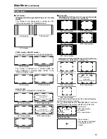
*1 Available during HD-SDI input signals.
*2 Available during VIDEO (NTSC) input. Closed captions appear as bright lines on line 21 when closed caption is

set to ON and underscan is also on.

*3 Opens the vector display during SDI signal input.

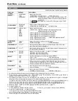
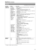
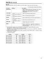
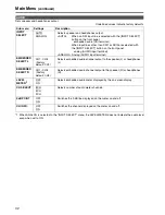
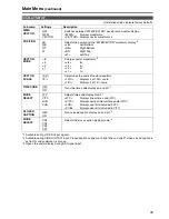
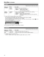
DISPLAY SETUP

Sub menu

Settings

Description

WFM/
VECTOR

OFF
WFM
VECTOR

Switches between “WFM/VECTOR” waveform and vector display. 
<WFM> Displays 

waveforms. 

<VECTOR> Displays vector waveforms.

*3

POSITION

LB
RB
RT
LT

Selects the position for the “WFM/VECTOR” waveform display.

*3

<LB>

Left Bottom

<RB> Right 

Bottom

<RT>

Right Top

<LT>

Left Top

VECTOR
MODE

× 8
× 4
× 2
× 1

Enlarges vector waveforms.

*3

<× 8>

<× 4>

<× 2>

<× 1>

VECTOR
SCALE

100%
75%

Determines the scale of vector waveform. 
<100%>

Displays it at 100% scale. 

<75%>

Displays it at 75% scale. 

TIME CODE

OFF
ON

Turns the time code display on and off.

*1

MODE
SELECT

LTC
VITC
LUB
VUB

Selects time code display mode.

*1

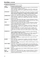
<LTC>

Displays linear time code (LTC). 

<VITC>

Displays vertical interval time code (VITC). 

<LUB>

Displays user bits included in LTC. 

<VUB>

Displays user bits included in VITC. 

CLOSED
CAPTION

OFF
ON

Turns closed caption display on and off.

*2

MODE
SELECT

CC4
CC3
CC2
CC1

Selects the cross caption display mode.

*2

Содержание BTLH1760P - LCD VIDEO MONITOR

Страница 1: ...Panasonic Broadcast BT LH1760P Menu Information ...

Страница 2: ...he PIXEL TO PIXEL mode is engaged 4 Various indications FILM mode This indicates that GAMMA SELECT is set to FILM 5 Various indications lock status This indicates that the control lock is on Note UNSUPPORT SIGNAL and NO SIGNAL may not be properly displayed Picture adjusting knob J page 9 Press or turn this knob to make adjustments The status display appears when the knob is pressed To clear the di...

Страница 3: ...meter indicates the audio level for SDI signals You can switch the level display on off and set the number of displayed channels using the menu The 0 dB line and channel display can be switched on off from the menu This is the menu display It disappears after 2 minutes of inaction You can change position of the display J page 22 MENU POSITION FUNCTION display F1 MARKER F2 WFM VECTOR F3 PIXEL TO PI...

Страница 4: ...ferent delimiter between seconds and frames is used Note Read errors are displayed as In VUB and LUB display modes BG8 BG7 BG6 BG5 BG4 BG3 BG2 BG1 appear in the stated order BG binary group The delimiter does not appear Note Read errors are displayed as Use the menu to display closed caption for VIDEO NTSC signals It also allows you to select display mode CC1 to CC4 Note Closed captions are not av...

Страница 5: ...ess ENTER 3 Press to select a sub menu and Press ENTER The settings in the sub menu change to green 4 Press to select a setting then press ENTER To cancel press MENU To return to the previous screen Push MENU Menu operations MAIN MENU How to Use the On Screen Menu continued ...

Страница 6: ...and press ENTER The setting in the sub menu changes to green 4 Press to select a USER1 to USER5 file to save the settings to and press ENTER The following screen appears 5 Select YES and press ENTER This saves the user data 1 Press MENU to display the MAIN menu 2 Press to select the SYSTEM CONFIG menu and press ENTER 3 Press to select the SETUP LOAD sub menu and press ENTER The setting in the sub ...

Страница 7: ...I D AUTOSETUP H POSITION V POSITION PHASE CLOCK WXGA XGA RESET AUDIO INPUT SELECT EMBEDDED SELECT L EMBEDDED SELECT R LEVEL METER CH SELECT 0 dB POINT CH INFO WHITE BALANCE VAR1 3 MARKER 16 9 4 3 BACK CENTER GPI PRESET1 GPI PRESET2 MARKER TYPE CROSS HATCH FUNCTION1 FUNCTION2 FUNCTION3 FUNCTION4 FUNCTION5 FUNCTION DISPLAY COLOR TEMP GAIN RED GAIN GREEN GAIN BLUE BIAS RED BIAS GREEN BIAS BLUE RESET ...

Страница 8: ...rea marker 80 80 area marker 88 89 area marker TYPE1 88 area marker TYPE2 BACK 2 NORMAL HALF BLACK Selects the background brightness around the marker NORMAL Normal background HALF 50 background brightness BLACK 0 background brightness black CENTER 2 OFF ON Displays the center marker OFF Turns the display off ON Turns the display on GPI PRESET1 5 4 3 13 9 14 9 CNSCO VISTA 95 16 9 93 16 9 90 16 9 8...

Страница 9: ...rker simultaneously Simultaneous display example The section becomes the MARKER BACK It controls the background of the marker selected with a 16 9 ratio Center marker Marker types 4 3 marker 13 9 marker 14 9 marker VISTA marker CNSCO marker VISTA marker CNSCO marker 95 Area marker 93 Area marker 90 Area marker 88 Area marker 80 Area marker TYPE1 Vertical 93 1 horizontal 93 TYPE2 Vertical Horizonta...

Страница 10: ...rs at the top left of the screen when FILM is selected FILM GAMMA 2 VARICAM OTHER Selects type of FILM gamma mode VARICAM For VARICAM use OTHER Other COLOR TEMP USER0 63 5 D93 D65 D56 VAR1 VAR2 VAR3 Selects color temperature USER 0 63 Adjustable settings 0 63 equivalent to a color temperature range of 3 000 9 300K D93 Equivalent to a color temperature of 9 300K D65 Equivalent to a color temperatur...

Страница 11: ...on is performed inside each field this mode is suitable for checking interlace status Sub menu Settings Description COLOR TEMP 1 USER0 6 D93 D65 D56 Selects the color temperature that will become the basis for adjustment USER 0 63 Adjustable settings 0 63 equivalent to a color temperature range of 3 000 9 300K D93 Equivalent to a color temperature of 9 300K D65 Equivalent to a color temperature of...

Страница 12: ...ottom RB Right Bottom RT Right Top LT Left Top STATUS DISPLAY CONTINUE 3SEC OFF OFF Sets display state for input signal status on screen menu CONTINUE Displayed at all times 3SEC OFF Displayed for 3 seconds after a status change OFF Not displayed SETUP LOAD USER5 1 2 USER4 1 2 USER3 1 2 USER2 1 2 USER1 1 2 FACTORY Loads saved factory defaults FACTORY or user data USER1 USER5 After loading user dat...

Страница 13: ...e gamma curve The display changes in the following order GAMMA STANDARD J GAMMA FILM J GAMMA STDIO PST J GAMMA STANDARD SD ASPECT Switches between 16 9 and 4 3 1 SCAN Switches between UNDER SCAN and NORMAL SCAN 1 SUB WINDOW Sets the split screen function 1 The display changes in the following order SINGLE J FULL PART J STILL J SINGLE WFM VECTOR Displays waveform or vector display MARKER Turns the ...

Страница 14: ... to indicate that operation is disabled If you select RGB COMP or DVI COMP while motion picture is displayed in sub window the screen returns to a single screen display Selecting something other than RGB COMP or DVI COMP opens the split screen mode and a still image is blacked out WFM VECTOR During SUB WINDOW and PIXEL TO PIXEL mode operation INVALID FUNCTION appears to indicate that operation is ...

Страница 15: ...PTION CC1 CC2 CC3 CC4 CC OFF HV DELAY This displays the blanking period Each press of the button changes the display as follows H blanking display J V blanking display J H and V blanking display J no blanking display SUB WINDOW Opening the SUB WINDOW function splits the screen main window in two as shown below to enable comparison of a recorded still image with live video Use the SUB WINDOW settin...

Страница 16: ...ssigned to any of the FUNCTION1 to FUNCTION5 buttons These examples show 16 9 aspect ratio images 1 Displayed only for SDI signal input PART Resizes the main window to show only its center to also display a second image two sub windows Normal window main window Before image input two sub windows After image input two sub windows Crops the image to show its center part The cropped main window image...

Страница 17: ...Underlined values indicate factory defaults 1 The following settings are disabled in PIXEL TO PIXEL mode Setting ANAMO to ON and setting SCAN to UNDER in VIDEO CONFIG Any HV DELAY setting in FUNCTION MARKER display 2 Enabled during SDI1 SDI2 and YPBPR input PIXEL POSITION display position sequence PIXEL POSITION J J J J J Sub menu Settings Description PIXEL TO PIXEL 1 2 OFF ON Tailors the image di...

Страница 18: ...onsist of 1 line and are spaced 80 dots apart fixed value Each press of the button FUNCTION1 to FUNCTION5 to which the CROSS HATCH has been assigned turns the function on and off Each press of the FUNCTION button to which the CROSS HATCH function is assigned changes the display as shown HD SD 16 9 mode SD 4 3 mode 1st press 2nd press Light cross hatch Dense cross hatch 3rd press back to original i...

Страница 19: ...elected under YPBPR RGB in the INPUT SELECT menu MONO operation when input signal is PC GPI Sub menu Settings Description GPI CONTROL DISABLE ENABLE Enables and disables GPI functions DISABLE Disabled ENABLE Enabled GPI1 GPI8 UNDEF MARKER1 ON OFF MARKER2 ON OFF MARKER BACK HALF MARKER BACK BLACK CENTER MARKER INPUT SEL VIDEO INPUT SEL SDI1 INPUT SEL SDI2 INPUT SEL YPBPR RGB INPUT SEL DVI D SD ASPE...

Страница 20: ...VIDEO Selects the video RGB signal RGB COMP Selects the PC RGB signal COMPONENT LEVEL SMPTE B75 B00 Selects YPBPR component signal input level SMPTE Signal level complies with SMPTE and PB and PR are 0 7 Vp p at 100 chroma B75 Select this when connecting a Betacam or similar device with a setup function Adjusts the interior of the monitor to the 7 5 setup level to suit the black level B00 Select t...

Страница 21: ...ect YES to perform AUTOSETUP H POSITION 0 60 Factory preset settings 30 Adjusts horizontal image display position 2 V POSITION 0 60 Factory preset settings 30 Adjusts vertical image display position 2 PHASE 0 31 Factory preset settings 16 Adjusts the clock phase in 1 32 clock period increments 2 CLOCK 700 1800 Factory preset settings 3 Adjusts the sampling clock in dot units 2 WXGA XGA XGA WXGA Sw...

Страница 22: ... selected with the INPUT SELECT button on the front panel analog AUDIO input terminal ANALOG Analog AUDIO input terminal EMBEDDED SELECT L CH1 CH8 Factory default CH1 Selects embedded audio channel output to the speaker L or headphones L EMBEDDED SELECT R CH1 CH8 Factory default CH2 Selects embedded audio channel output to the speaker R or headphones R LEVEL METER 1 OFF ON Selects embedded audio m...

Страница 23: ... Selects the position for the WFM VECTOR waveform display 3 LB Left Bottom RB Right Bottom RT Right Top LT Left Top VECTOR MODE 8 4 2 1 Enlarges vector waveforms 3 8 8 4 4 2 2 1 1 VECTOR SCALE 100 75 Determines the scale of vector waveform 100 Displays it at 100 scale 75 Displays it at 75 scale TIME CODE OFF ON Turns the time code display on and off 1 MODE SELECT LTC VITC LUB VUB Selects time code...

Страница 24: ...XX indicates the number of hours XXXXXX 262800H about 30 years 262800 or greater number results in OVER CONTROL Sub menu Settings Description CONTROL LOCAL REMOTE Selects operation with control clock LOCAL Enables front panel operation REMOTE Enables remote operation front panel operation is locked 1 LOCAL ENABLE 2 DISABLE INPUT Selects the disabled operation on the front panel when selecting REMO...

Отзывы: