background image

19

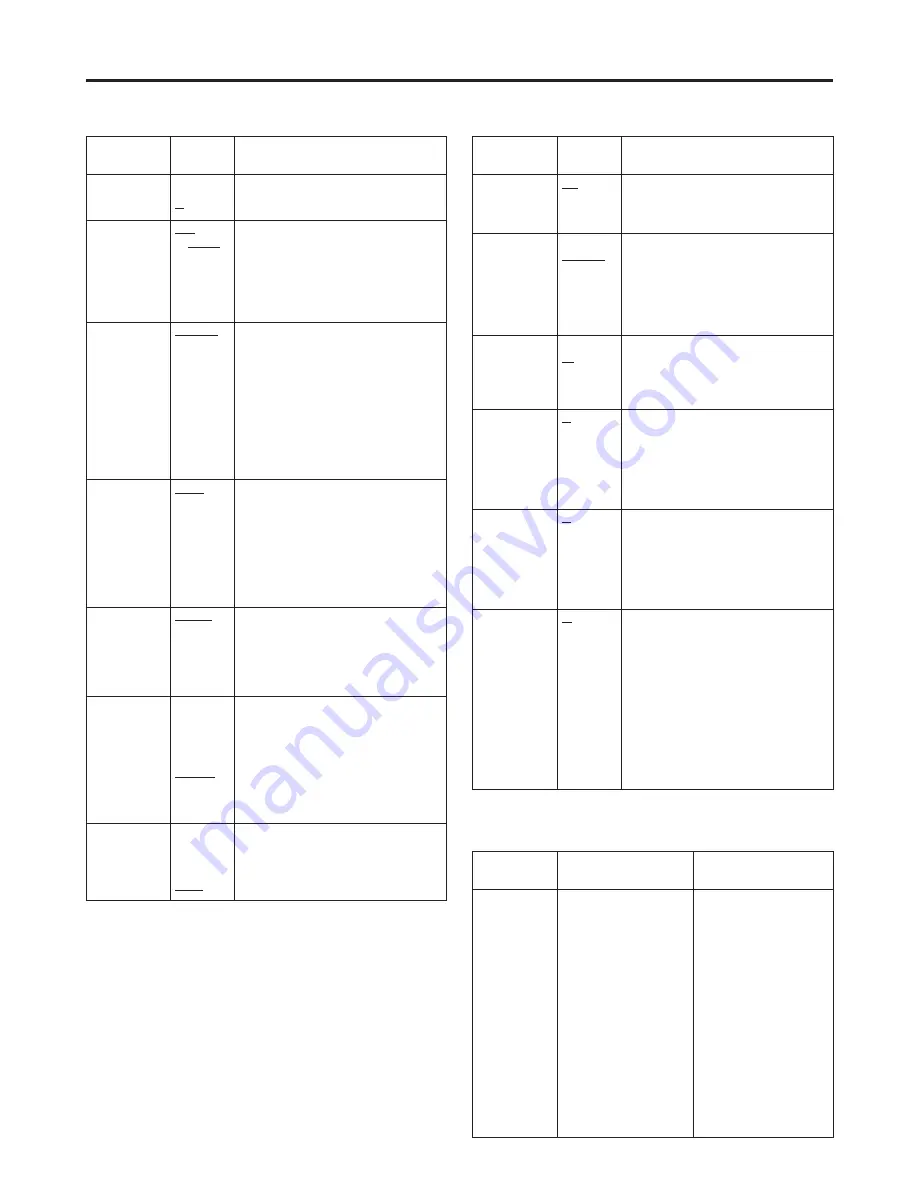
Item

Setting

Description

GPI1-8

UNDEF
MARKER1 ON/OFF
MARKER2 ON/OFF
MARKER BACK HALF
MARKER BACK BLACK
CENTER MARKER
INPUT SEL. SDI1
INPUT SEL. SDI2
INPUT SEL. VIDEO
INPUT SEL. YPBPR/RGB
SD ASPECT
HD ZOOM
BACKLIGHT MIN.
R.TALLY
G.TALLY
MONO ON/OFF
GAMMA SELECT
WFM ON/OFF

For allocating particular
functions to particular pins
when remote control
operations are to be
performed using the GPI
signals.  For details, refer to
“REMOTE specifications”
(page 22).

GPI

MAIN MENU

The underlined setting indicates the factory setting mode.

Item

Setting

Description

BACKLIGHT

0

:

60

For adjusting the backlight brightness to a
level from 0 to 60.  The higher the setting,
the brighter the backlight.

FUNCTION

WFM

ON/OFF

HV DELAY
UNDEF

For setting the function to be allocated to
the FUNCTION/ENTER button.

WFM ON/OFF:

The Y signal (luminance)
waveforms are displayed.

HV DELAY:

The blanked parts of the
images are displayed.

UNDEF:

No function is allocated.

WFM

FUNCTION
GPI

For selecting whether the Y signal
(luminance) waveforms are to be displayed
using the FUNCTION/ENTER button or
from the GPI connector.

FUNCTION:

The waveforms are displayed
using the FUNCTION/ENTER
button.

GPI:

The operations are performed
from the GPI connector.  For
details, refer to “REMOTE
specifications” (page 22).

HD ZOOM

FRONT
GPI

For selecting whether the HD ZOOM
function is to be operated using the HD
ZOOM/

X

button or from the GPI connector.

FRONT:

The function is operated using the
HD ZOOM/

X

button.

GPI:

The operations are performed from
the GPI connector.  For details,
refer to “REMOTE specifications”
(page 22).

PEAKING/ PHASE

PEAKING
PHASE

For selecting the PEAKING or PHASE
function for the image control.

PEAKING:

The PEAKING function is
allocated to the control.

PHASE:

The PHASE function is allocated
to the control.

USER MODE
LOAD

USER5
USER4
USER3
USER2
USER1
FACTORY

For calling the file in which the user data is
stored.

USER1-5:

These are the files in which the
user has stored data.  If the user
data has not yet been stored,
the settings are the same as the
ones in the FACTORY file.

FACTORY:

This file contains the factory
settings.

USER MODE SAVE

USER5
USER4
USER3
USER2
USER1

For saving the user data.

SYSTEM CONFIG

Item

Setting

Description

BATTERY REMAIN

OFF
ON

For selecting whether to display the
remaining battery charge.

OFF:

The remaining charge is not displayed.

ON:

The remaining charge is displayed.

STATUS DISPLAY

CONTINUE
3SEC. OFF
OFF

For setting how long the status display is to
remain on the screen.

CONTINUE:

The status display appears
continuously at all times.

3SEC.OFF:

The status display appears for
three seconds.

OFF:

The status display does not appear.

CRCC MESSAGE

OFF
ON

For selecting whether a message is to be
displayed when a CRCC error has been
detected.

OFF:

A CRCC error message is not displayed.

ON:

A CRCC error message is displayed.

MENU POSITION

LT
CENTER
LB
RB
RT

For setting the menu display position.

LT:

The menu is displayed at the top left.

CENTER:

The menu is displayed in the centre.

LB:

The menu is displayed at the bottom left.

RB:

The menu is displayed at the bottom right.

RT:

The menu is displayed at the top right.

STATUS POSITION

LT
CENTER
LB
RB
RT

For setting the status display position.

LT:

The menu is displayed at the top left.

CENTER:

The menu is displayed in the centre.

LB:

The menu is displayed at the bottom left.

RB:

The menu is displayed at the bottom right.

RT:

The menu is displayed at the top right.

ROTARY
POSITION

LB
CB
RB
RT
LT
CENTER
OFF

For setting the display position of the
settings when images have been adjusted
using the image controls.

LB:

The settings are displayed at the
bottom left.

CB:

The settings are displayed below the centre.

RB:

The settings are displayed at the
bottom right.

RT:

The settings are displayed at the top right.

LT:

The settings are displayed at the top left.

CENTER:

The settings are displayed in the centre.

OFF:

The settings are not displayed.

OSD CONFIG

Содержание BT-LH900E

Страница 1: ...ng to connect operate or adjust this product please read these instructions completely BT LH900E Liquid Crystal Video Monitor POWER INPUT MENU EXIT ENTER HD ZOOM BLUE FUNCTION PEAK PHASE CHROMA BRIGHT CONTRAST VQT0G65 ...

Страница 2: ...eze niet gewoon weggooien maar dient u deze als klein chemisch afval weg te doen Attention Attentie DO NOT REMOVE PANEL COVER BY UNSCREWING To reduce the risk of electric shock do not remove cover No user serviceable parts inside Refer servicing to qualified service personnel CAUTION TO REDUCE THE RISK OF FIRE OR SHOCK HAZARD AND ANNOYING INTERFERENCE USE THE RECOMMENDED ACCESSORIES ONLY CAUTION O...

Страница 3: ...echnology The screen has effective pixels that cover more than 99 99 of its area but pixels may be missing or remain permanently lit red blue and or green in less than 0 01 of the area This is not indicative of malfunctioning The panel which protects the liquid crystal display has been specially treated Do not wipe it with hard cloths or rub it heavily as this will damage the surface of the panel ...

Страница 4: ...rted In addition to its two lines of SDI input connectors automatic HD SD switching the monitor provides one line each of component input connectors and composite input connectors Wide viewing angle The monitor can display excellent images over an angle extending for 170 degrees in both the top bottom and left right directions High definition images At 1024 a 768 dots XGA the large number of scree...

Страница 5: ... 2 MENU EXIT button This button is used to display the menus When it is pressed while a menu is already displayed the menu display is cleared or the menu at one hierarchical level above is restored When the button is pressed while a setting is being changed the setting established prior to the change is restored and the menu at one hierarchical level above is restored 3 HD ZOOM X X button This but...

Страница 6: ...an be set The default setting is 30 However the brightness cannot be adjusted when blanking is displayed using the HV DELAY function 4 CONTRAST This control is used to adjust the image contrast Any value from 0 to 60 can be set The default setting is 50 5 FUNCTION ENTER button This button is used to enter changes or settings while a menu is displayed If there is no menu display the button s functi...

Страница 7: ...itor and at its bottom where the main controls are removed A removable screw spacer is provided in one of the screw holes in the bottom of the monitor and this supports a UNC1 4 20 screw To secure the tripod use the hole that fits the diameter of the fastening screw on the tripod Power switch This is the power switch 8 GPI connector When GPI signals are connected here external operations can be pe...

Страница 8: ... it clicks into place 3 Remove the two screws and remove the main controls from the main unit These two screws cannot be removed from the main controls themselves 4 Use the two screws to secure the main controls to the right panel 2 6 Remove the screws on the right panel of the main unit Secure the two screws which were removed in step 2 in the screw holes on the bottom of the monitor 5 Plug the c...

Страница 9: ...tery mount 3 Secure the V mount adapter using the four screws and then secure the two screws of the connector section V mount adapter This connector is not used 2 Insert the battery pack and slide it in the direction of the arrow Reference To remove the battery pack slide it in the opposite direction to the one in which it was attached while keeping the release lever on the battery holder pulled d...

Страница 10: ... power supply other than the AJ B75 AC adapter check the pin signals of its external DC input connector and use the polarities correctly Notes DC cords should be no longer than 2 meters Use of cords any longer than 2 meters may result in noise appearing on the screen Power from the AC adapter takes precedence when both a battery pack and AC adapter have been connected It is also possible to attach...

Страница 11: ...ntrols are displayed instead S D I 1 1 0 8 0 6 0 I C R C C D C 1 5 0 V 6 0 1 2 3 1 Channel and signal format The channel which has been selected whether SDI 1 SDI 2 VIDEO YPBPR or RGB is displayed here Indicated as the signal format is the format of the signals which have been input However UNSUPPORTED SIGNAL will appear if signals which are not supported have been input Similarly UNSUPPORTED SIGN...

Страница 12: ...ent is made by turning an already popped out control It is cleared when a control is pressed again and returned to its original position It is also cleared when a popped out control is not touched for 10 seconds C O N T R A S T 5 0 Menu setting Signals whose input is accepted Status display AUTO All supported signals The format of the input signals is displayed 1080 50I 1080 50I 1080 50I 1080 25P ...

Страница 13: ...layed in green 3 M A R K E R M A R K E R S E L E C T M E N U M A R K E R 1 6 9 O F F M A R K E R 4 3 O F F M A R K E R B A C K N O R M A L C E N T E R M A R K E R O F F G P I P R E S E T 1 8 0 G P I P R E S E T 2 8 0 E X I T S E L E N T E R 1 M E N U E N T E R XW Use the HD ZOOM X button and BLUE W button to change the setting and press the FUNCTION ENTER button to enter the change Alternatively t...

Страница 14: ...N T E R XW When the file whose data is to be saved is selected from the USER1 to USER5 files and the FUNCTION ENTER button is then pressed the screen shown below appears 3 U S E R M O D E S A V E U S E R 1 Y E S N O E X I T S E L S E T 1 M E N U E N T E R XW Displayed in green Loading the user data Using menu operations see page 13 select USER MODE LOAD on the SYSTEM CONFIG screen and press the FU...

Страница 15: ... COLOR TEMP SHARPNESS MODE CONTROL LOCAL ENABLE BACKLIGHT TIME SD ASPECT I P MODE MONO BACKLIGHT FUNCTION WFM HD ZOOM PEAKING PHASE USER MODE LOAD GPI1 GPI2 GPI3 GPI4 GPI5 MAIN VIDEO CONFIG SYSTEM CONFIG MARKER BACK USER MODE SAVE OSD CONFIG GPI INPUT SELECT CONTROL GPI PRESET1 GPI PRESET2 GPI6 GPI7 GPI8 SDI1 FORMAT SDI2 FORMAT VIDEO FORMAT YPBPR RGB MODE FORMAT COMPONENT LEVEL RGB SYNC CENTER MAR...

Страница 16: ...e are displayed 95 The 95 area markers are displayed 93 The 93 area markers are displayed 88 The 88 area markers are displayed 80 The 80 area markers are displayed GPI PRESET2 4 3 13 9 14 9 95 93 88 80 For setting the markers to be displayed if when MARKER2 ON OFF has been allocated to any item and GPI has been selected as the MARKER SELECT item setting on the GPI screen the corresponding pin has ...

Страница 17: ...s set by the MARKER BACK item 95 area markers 93 area markers 88 area markers 80 area markers 4 3 markers These appear when SD signals with a 4 3 aspect ratio are supplied Centre marker Centre marker This appears at the centre of the image Dotted lines are displayed as the markers Dotted lines are displayed as the markers 16 9 markers These appear when HD signals or when SD signals with a 16 9 asp...

Страница 18: ...in the horizontal direction This item enables two settings one for the VIDEO input signals and one for other signals to be stored in the memory Notes While this item s setting is selected the only information displayed on the screen is this item which appears at the bottom left regardless of the MENU POSI setting selected on the OSD screen The sharpness can be set for VIDEO and all other input cha...

Страница 19: ... file in which the user data is stored USER1 5 These are the files in which the user has stored data If the user data has not yet been stored the settings are the same as the ones in the FACTORY file FACTORY This file contains the factory settings USER MODE SAVE USER5 USER4 USER3 USER2 USER1 For saving the user data SYSTEM CONFIG Item Setting Description BATTERY REMAIN OFF ON For selecting whether...

Страница 20: ... at the same time Once the three items have been set to OFF it is no longer possible to set a fourth item to OFF It is not possible to set all the inputs to OFF Item Setting Description SDI2 1 OFF ON For setting whether the SDI 2 signals can be selected when the channels are to be switched using the INPUT button OFF The SDI 2 signals cannot be selected ON The SDI 2 signals can be selected FORMAT A...

Страница 21: ...has been superimposed onto the G signal EXT The sync signal is accepted at the SYNC connector among the analogue component RGBS connectors MAIN MENU The underlined setting indicates the factory setting mode Item Setting Description FORMAT AUTO 1080 60I 1080 50I 1080 30P 1080 25P 1080 24P 1080 24PsF 1035 60I 720 60P 576 50I 480 60P 480 60I For selecting the signals whose input is to be accepted in ...

Страница 22: ...the input channel to VIDEO Note This function is not valid when OFF has been selected as the VIDEO item see page 20 setting on the FORMAT screen INPUT SEL YPBPR RGB This switches the input channel to ANALOGUE Note This function is not valid when OFF has been selected as the YPBPR RGB item see page 20 setting on the FORMAT screen INPUT SEL SDI1 This switches the input channel to SDI 1 Note This fun...

Страница 23: ...f the image controls and tally lamps flash at 1 second intervals Countermeasure Turn off the power and turn it back on If the error display persists contact a Panasonic Service Centre Low remaining battery charge warning error When this warning error appears If the battery voltage is 10 5V to 11 3V If the remaining charge is less than 10 when an Anton Bauer digital battery is being used The remain...

Страница 24: ...ility for a long time to come be absolutely sure to conduct the maintenance and inspections described here 1 Necessity for periodic maintenance and servicing A backlight power supply is used in this LCD monitor This part which is a consumable will deteriorate over time and lead to a reduced level of performance and failure For this reason do not confine the maintenance activities to the kind of af...

Страница 25: ...d out facility GPI D sub 9 pins RS 232C D sub 9 pins DC input XLR 4 pins Battery holder Battery holder made by Anton Bauer Signal formats supported Formats when SDI signals are used 480 59 94I 576 50I 720 60P 720 59 94P 1035 60I 1035 59 94I 1080 24psF 1080 23 98psF 1080 24P 1080 23 98P 1080 25P 1080 30P 1080 29 97P 1080 50I 1080 60I 1080 59 94I Formats when RGB signals are used 480 59 94I 576 50I ...

Страница 26: ...26 MEMO ...

Страница 27: ...27 MEMO ...

Страница 28: ...S1103T0 Matsushita Electric Industrial Co Ltd Web Site http www panasonic co jp global Printed in Japan E ...

Отзывы: