background image

4

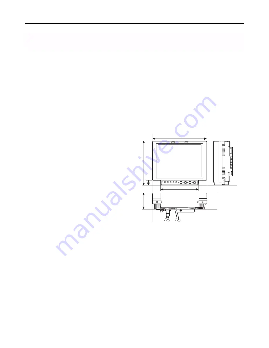
218 mm

176 mm

18 mm

150 mm

65 mm

Introduction

Designed for use in broadcasting and commercial applications, the model BT-LH900P is a slim-line and lightweight liquid
crystal video monitor with an 8.4-type liquid crystal screen.
For use, secure it in place by, for instance, installing it in a rack by using the optional rack-mounting adaptors BT-MA900G or
mounting it on a tripod.  (For details, refer to the instructions in the operation guide of the BT-MA900G.)

Slim design, light weight, compact size, low
power consumption and driven by DC
power

Since this monitor uses an LCD panel, it has a slim
design, light weight and compact size.  Furthermore,
while supporting HD specifications, it has a low power
consumption, and it can be operated using DC power:
these are all features which make the monitor useful in
outdoor locations.

Multiple formats supported

In addition to its two lines of SDI input connectors
(automatic HD/SD switching), the monitor provides one
line each of component input connectors and composite
input connectors.

Wide viewing angle

The monitor can display excellent images over an angle
extending for 170 degrees in both the top-bottom and left-
right directions.

High-definition images

At 1024 

a

768 dots (XGA), the large number of screen

pixels ensures a high color reproducibility and tonal
range.

Functions

The main controls can be relocated to the bottom surface
or right panel of the main unit to support monitor
specifications, viewfinder specifications and other
applications.

The monitor comes with a film gamma correction
function to support its use as the viewfinder for the AJ-
HDC27F.  (For further details, consult with your dealer
or a Panasonic Service Center.)

Waveform monitor functions provided

Marker functions and blue-only function incorporated

RS-232C external control, remote control using GPI
connector enabled

Outline diagrams of monitor as seen from
three sides

Содержание BT-LH900

Страница 1: ...mpting to connect operate or adjust this product please read these instructions completely BT LH900P Liquid Crystal Video Monitor POWER INPUT MENU EXIT ENTER HD ZOOM BLUE FUNCTION PEAK PHASE CHROMA BRIGHT CONTRAST ...

Страница 2: ...tion instructions and do not make any unauthorized modifications This equipment has been tested and found to comply with the limits for a class A digital device pursuant to Part 15 of the FCC Rules These limits are designed to provide reasonable protection against harmful interference when the equipment is operated in a commercial environment This equipment generates uses and can radiate radio fre...

Страница 3: ...sion technology The screen has effective pixels that cover more than 99 99 of its area but pixels may be missing or remain permanently lighted red blue and or green in less than 0 01 of the area This is not indicative of malfunctioning The panel which protects the liquid crystal display has been specially treated Do not wipe it with hard cloths or rub it heavily as this will damage the surface of ...

Страница 4: ...rted In addition to its two lines of SDI input connectors automatic HD SD switching the monitor provides one line each of component input connectors and composite input connectors Wide viewing angle The monitor can display excellent images over an angle extending for 170 degrees in both the top bottom and left right directions High definition images At 1024 a 768 dots XGA the large number of scree...

Страница 5: ...pped 2 MENU EXIT button This button is used to display the menus When it is pressed while a menu is already displayed the menu display is cleared or the menu at one hierarchical level above is restored When the button is pressed while a setting is being changed the setting established prior to the change is restored and the menu at one hierarchical level above is restored 3 HD ZOOM X X button This...

Страница 6: ...n be set The default setting is 30 However the brightness cannot be adjusted when blanking is displayed using the HV DELAY function 4 CONTRAST This control is used to adjust the image contrast Any value from 0 to 60 can be set The default setting is 50 5 FUNCTION ENTER button This button is used to enter changes or settings while a menu is displayed If there is no menu display the button s functio...

Страница 7: ...nitor and at its bottom where the main controls are removed A removable screw spacer is provided in one of the screw holes in the bottom of the monitor and this supports a UNC1 4 20 screw To secure the tripod use the hole that fits the diameter of the fastening screw on the tripod Power switch This is the power switch 7 GPI connector When GPI signals are connected here external operations can be p...

Страница 8: ... it clicks into place 3 Remove the two screws and remove the main controls from the main unit These two screws cannot be removed from the main controls themselves 4 Use the two screws to secure the main controls to the right panel 2 6 Remove the screws on the right panel of the main unit Secure the two screws which were removed in step 2 in the screw holes on the bottom of the monitor 5 Plug the c...

Страница 9: ...ount Metal battery mount 3 Secure the V mount adapter using the four screws and then secure the two screws of the connector section V mount adapter 2 Insert the battery pack and slide it in the direction of the arrow Reference To remove the battery pack slide it in the opposite direction to the one in which it was attached while keeping the release lever on the battery holder pulled down all the w...

Страница 10: ... ON 3 Set the unit s power switch to ON When using an external power supply other than the AJ B75 AC adapter check the pin signals of its external DC input connector and use the polarities correctly Notes Power from the AC adapter takes precedence when both a battery pack and AC adapter have been connected It is also possible to attach remove a battery while the AC adapter is being used When using...

Страница 11: ...ntrols are displayed instead S D I 1 1 0 8 0 6 0 I C R C C D C 1 5 0 V 6 0 1 2 3 1 Channel and signal format The channel which has been selected whether SDI 1 SDI 2 VIDEO YPBPR or RGB is displayed here Indicated as the signal format is the format of the signals which have been input However UNSUPPORTED SIGNAL will appear if signals which are not supported have been input Similarly UNSUPPORTED SIGN...

Страница 12: ...ent is made by turning an already popped out control It is cleared when a control is pressed again and returned to its original position It is also cleared when a popped out control is not touched for 10 seconds C O N T R A S T 5 0 Menu setting Signals whose input is accepted Status display AUTO All supported signals The format of the input signals is displayed 1080 50I 1080 50I 1080 50I 1080 25P ...

Страница 13: ...played in green 3 M A R K E R M A R K E R S E L E C T M E N U M A R K E R 1 6 9 O F F M A R K E R 4 3 O F F M A R K E R B A C K N O R M A L C E N T E R M A R K E R O F F G P I P R E S E T 1 8 0 G P I P R E S E T 2 8 0 E X I T S E L E N T E R 1 M E N U E N T E R XW Use the HD ZOOM X button and BLUE W button to change the setting and press the FUNCTION ENTER button to enter the change Alternatively ...

Страница 14: ...N T E R XW When the file whose data is to be saved is selected from the USER1 to USER5 files and the FUNCTION ENTER button is then pressed the screen shown below appears 3 U S E R M O D E S A V E U S E R 1 Y E S N O E X I T S E L S E T 1 M E N U E N T E R XW Displayed in green Loading the user data Using menu operations see page 13 select USER MODE LOAD on the SYSTEM CONFIG screen and press the FU...

Страница 15: ... COLOR TEMP SHARPNESS MODE CONTROL LOCAL ENABLE BACKLIGHT TIME SD ASPECT I P MODE MONO BACKLIGHT FUNCTION WFM HD ZOOM PEAKING PHASE USER MODE LOAD GPI1 GPI2 GPI3 GPI4 GPI5 MAIN VIDEO CONFIG SYSTEM CONFIG MARKER BACK USER MODE SAVE OSD CONFIG GPI INPUT SELECT CONTROL GPI PRESET1 GPI PRESET2 GPI6 GPI7 GPI8 SDI1 FORMAT SDI2 FORMAT VIDEO FORMAT YPBPR RGB MODE FORMAT COMPONENT LEVEL RGB SYNC CENTER MAR...

Страница 16: ... are displayed 95 The 95 area markers are displayed 93 The 93 area markers are displayed 88 The 88 area markers are displayed 80 The 80 area markers are displayed GPI PRESET2 4 3 13 9 14 9 95 93 88 80 For setting the markers to be displayed if when MARKER2 ON OFF has been allocated to any item and GPI has been selected as the MARKER SELECT item setting on the GPI screen the corresponding pin has b...

Страница 17: ...s set by the MARKER BACK item 95 area markers 93 area markers 88 area markers 80 area markers 4 3 markers These appear when SD signals with a 4 3 aspect ratio are supplied Center marker Center marker This appears at the center of the image Dotted lines are displayed as the markers Dotted lines are displayed as the markers 16 9 markers These appear when HD signals or when SD signals with a 16 9 asp...

Страница 18: ...the horizontal direction This item enables two settings one for the VIDEO input signals and one for other signals to be stored in the memory Notes While this item s setting is selected the only information displayed on the screen is this item which appears at the bottom left regardless of the MENU POSI setting selected on the OSD screen The sharpness can be set for VIDEO and all other input channe...

Страница 19: ... file in which the user data is stored USER1 5 These are the files in which the user has stored data If the user data has not yet been stored the settings are the same as the ones in the FACTORY file FACTORY This file contains the factory settings USER MODE SAVE USER5 USER4 USER3 USER2 USER1 For saving the user data SYSTEM CONFIG Item Setting Description BATTERY REMAIN OFF ON For selecting whether...

Страница 20: ...o OFF at the same time Once the three items have been set to OFF it is no longer possible to set a fourth item to OFF It is not possible to set all the inputs to OFF Item Setting Description SDI2 1 OFF ON For setting whether the SDI 2 signals can be selected when the channels are to be switched using the INPUT button OFF The SDI 2 signals cannot be selected ON The SDI 2 signals can be selected FOR...

Страница 21: ... has been superimposed onto the G signal EXT The sync signal is accepted at the SYNC connector among the analog component RGBS connectors MAIN MENU The underlined setting indicates the factory setting mode Item Setting Description FORMAT AUTO 1080 60I 1080 50I 1080 30P 1080 25P 1080 24P 1080 24PsF 1035 60I 720 60P 576 50I 480 60P 480 60I For selecting the signals whose input is to be accepted in t...

Страница 22: ... the input channel to VIDEO Note This function is not valid when OFF has been selected as the VIDEO item see page 20 setting on the FORMAT screen INPUT SEL YPBPR RGB This switches the input channel to ANALOG Note This function is not valid when OFF has been selected as the YPBPR RGB item see page 20 setting on the FORMAT screen INPUT SEL SDI1 This switches the input channel to SDI 1 Note This func...

Страница 23: ...f the image controls and tally lamps flash at 1 second intervals Countermeasure Turn off the power and turn it back on If the error display persists contact a Panasonic service center Low remaining battery charge warning error When this warning error appears If the battery voltage is 10 5V to 11 3V If the remaining charge is less than 10 when an Anton Bauer digital battery is being used The remain...

Страница 24: ...ir ability for a long time to come be absolutely sure to conduct the maintenance and inspections described here 1 Necessity for periodic maintenance and servicing A backlight power supply is used in this LCD monitor This part which is a consumable will deteriorate over time and lead to a reduced level of performance and failure For this reason do not confine the maintenance activities to the kind ...

Страница 25: ...tched out facility GPI D sub 9 pins RS 232C D sub 9 pins DC input XLR 4 pins Battery holder Battery holder made by Anton Bauer Signal formats supported Formats when SDI signals are used 480 59 94I 576 50I 720 60P 720 59 94P 1035 60I 1035 59 94I 1080 24PsF 1080 23 98PsF 1080 24P 1080 23 98P 1080 25P 1080 30P 1080 29 97P 1080 50I 1080 60I 1080 59 94I Formats when RGB signals are used 480 59 94I 576 ...

Страница 26: ...26 MEMO ...

Страница 27: ...27 MEMO ...

Страница 28: ...0068 323 436 3500 Government Marketing Department 52 West Gude Drive Rockville MD 20850 301 738 3840 Broadcast PARTS INFORMATION ORDERING 9 00 a m 5 00 p m EST 800 334 4881 24 Hr Fax 800 334 4880 Emergency after hour parts orders 800 334 4881 TECHNICAL SUPPORT Emergency 24 Hour Service 800 222 0741 Panasonic Canada Inc 5770 Ambler Drive Mississauga Ontario L4W 2T3 905 624 5010 Panasonic de Mexico ...

Отзывы: