23
BL-C111A/BL-C131A
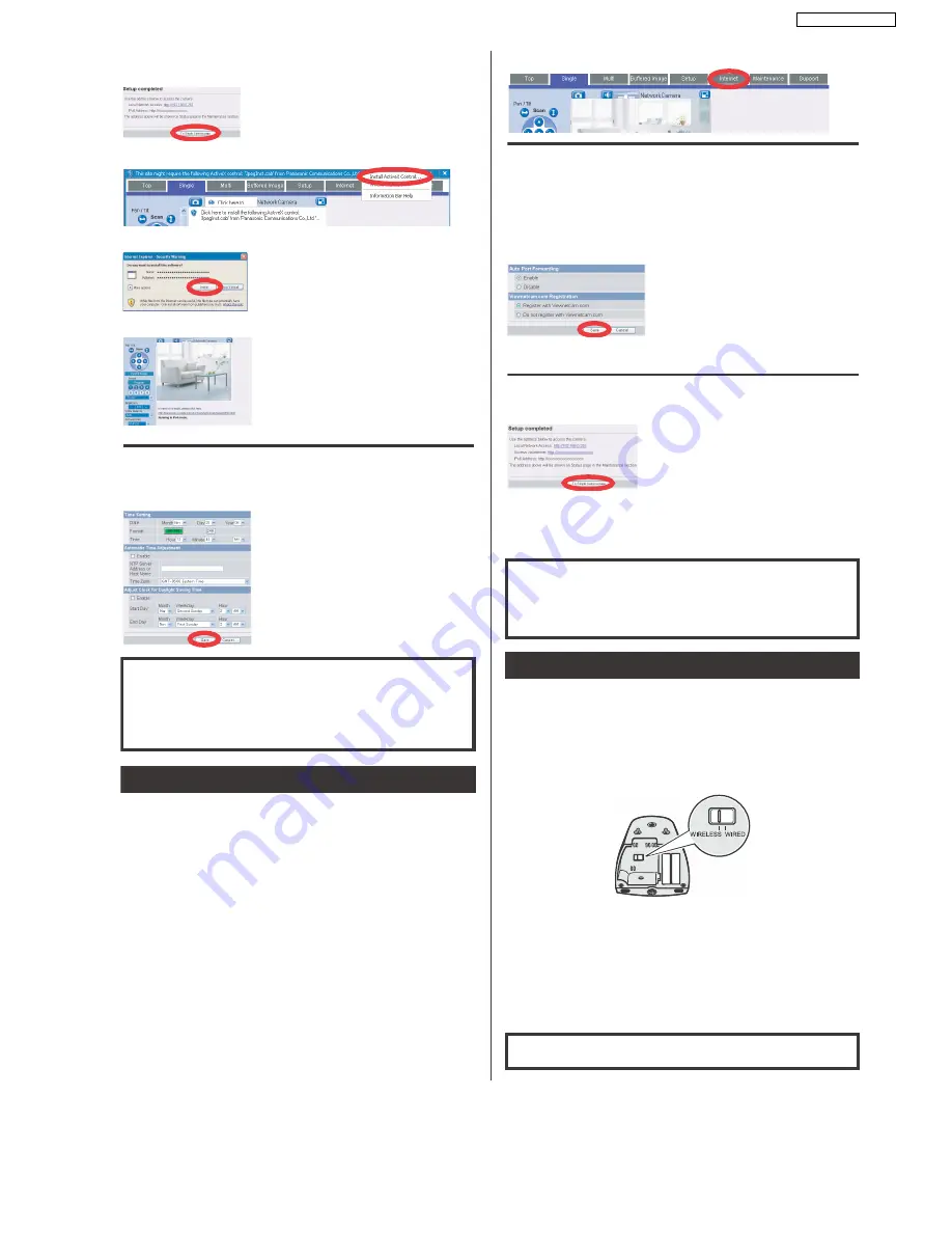
8. When [Setup completed] is displayed, click [To Single
Camera page].
• If the following ActiveX
®
Controls dialog is displayed, click [Install ActiveX Control...].
• When the following Security Warning is displayed, click [Install].
• The camera image is displayed.
9. Click the [Setup] tab, click [Date and Time] on the left
side of the screen, then set the camera’s date and
time. Click [Save] when finished.
To configure the camera for access from the Internet or from a mobile
phone, continue with the following steps.
Note:
• In order to configure the camera for access over the Internet using these instructions, your
router must be UPnP
™
compatible and must have its UPnP
™
feature turned on (it is turned
off by default on most routers). For more information, refer to the operating instructions
included with your router.
• To configure the camera for access over the Internet using a router that does not support
UPnP
™
, refer to Section 4 Configuring the Camera for Access from the Internet in the
Operating Instructions on the CD-ROM for general information, and refer to the operating
instructions included with your router.
• Disable the maximum idle time setting on your router if you have a PPPoE or PPTP
connection to your Internet Service Provider.
1. Click the [Internet] tab at the top of the camera screen.
2. Select [Enable] under [Auto Port Forwarding], select
[Register with Viewnetcam.com] under
[Viewnetcam.com Registration], then click [Save].
• When the dialog about the camera’s port number changing is displayed, click [OK].
• The camera and router will begin configuring themselves via UPnP
™
.
• If you select to register with Viewnetcam.com, click [Go to Viewnetcam.com
Registration page] when it is displayed. The Viewnetcam.com website will open
automatically. Follow the on-screen instructions to register.
3. When [Setup completed] is displayed, click [To Single
Camera page].
• If you enabled [Auto Port Forwarding], the camera’s port number may have changed.
Do not forget the addresses displayed here.
• To confirm that the camera can be accessed from the Internet using a PC, use a PC
not connected to your network and access the camera using the address displayed
here.
After configuring the camera’s wireless settings, confirm that the
camera can be accessed wirelessly.
1. Disconnect the LAN cable from the camera, and
unplug the AC adaptor from the power outlet.
2. Set the WIRELESS/WIRED switch on the bottom of the
camera to WIRELESS.
3. Plug the AC adaptor in to the power outlet.
• Confirm that the indicator lights green after about 1 minute. If the indicator does not
light green, see 1.2 Camera Indicator Issues in the Troubleshooting Guide on the CD-
ROM.
4. Start your web browser and access the camera.
• Enter camera’s IP address that was displayed during setup, then press [Enter] on the
keyboard.
• If you cannot access the camera, see 1.4 Wireless Connection Issues (BL-C131A
Only) in the Troubleshooting Guide on the CD-ROM.
• You may need to restart your router in order to access the camera in wireless mode.
The camera’s IP address is displayed. This is the
IP address you must enter in your web browser to
access the camera. Do not forget this address.
This will install the ActiveX Controls needed to
display camera images properly. ActiveX Controls
must be installed to view MPEG-4 images,
MJPEG images, and to use audio features.
Congratulations! You have successfully set up the
camera and can now view camera images.
For more information, refer to 5.4 Setting the Date
and Time in the Operating Instructions on the CD-
ROM.
Setup is complete. To configure the camera for access from the
Internet, see “Access from Internet Configuration”. To confirm the
camera’s wireless connection (BL-C131A only), see “Confirming
Wireless Connection (BL-C131A Only)”.
If you are finished setting up the camera, return to the Installation
Guide and follow the instructions for mounting the camera.
Access from Internet Configuration
If you are interested in accessing your camera over
the Internet, we recommend using
Viewnetcam.com. Viewnetcam.com is a Dynamic
DNS service designed for use with Panasonic
Network Cameras, and is provided free of charge.
For more information about Viewnetcam.com,
refer to the Viewnetcam.com website
(http://www.viewnetcam.com) for information
about this service.
The camera’s IP addresses for local (LAN) and
Internet access are displayed. These are the IP
addresses you must enter in your web browser to
access the camera over the LAN or from the
Internet. Do not forget these addresses.
Setup is complete. To confirm the camera’s wireless connection
(BL-C131A only), see “Confirming Wireless Connection (BL-
C131A Only)”.
If you are finished setting up the camera, return to the Installation
Guide and follow the instructions for mounting the camera.
Confirming Wireless Connection (BL-C131A Only)
If you are finished setting up the camera, return to the Installation
Guide and follow the instructions for mounting the camera.
Содержание BL C131A - Network Camera - Pan
Страница 5: ...5 BL C111A BL C131A LENS BOARD I O BOARD ...
Страница 17: ...17 BL C111A BL C131A 5 Location of Controls and Components ...
Страница 18: ...18 BL C111A BL C131A 6 Installation Instructions ...
Страница 19: ...19 BL C111A BL C131A ...
Страница 21: ...21 BL C111A BL C131A 7 2 Connection ...
Страница 25: ...25 BL C111A BL C131A 1 It does not turn on when LED mode is OFF on web setup menu ...
Страница 26: ...26 BL C111A BL C131A 8 2 Indicator view Check ...
Страница 27: ...27 BL C111A BL C131A 8 3 LAN Block Check 8 3 1 Green Light On ...
Страница 28: ...28 BL C111A BL C131A 8 3 2 Orange Light Blinking 1 ...
Страница 29: ...29 BL C111A BL C131A 8 3 3 Orange Light Blinking 2 ...
Страница 30: ...30 BL C111A BL C131A 8 4 Camera Block Check ...
Страница 31: ...31 BL C111A BL C131A 8 5 Power Supply Block Check ...
Страница 32: ...32 BL C111A BL C131A 8 6 Other Operation Check 8 6 1 PAN Operation Check 8 6 2 TILT Operation Check ...
Страница 33: ...33 BL C111A BL C131A 8 7 Pyroelectric Infrared Sensor Check ...
Страница 34: ...34 BL C111A BL C131A 8 8 Sound Block Check ...
Страница 35: ...35 BL C111A BL C131A 8 9 RF Block Check BL C131A ...
Страница 64: ...64 BL C111A BL C131A M O1 O2 O3 P1 P2 P3 N1 N2 Power ON Start ...
Страница 73: ...73 BL C111A BL C131A 16 2 Cabinet and Electrical Parts Location BL C131A ...
Страница 74: ...74 BL C111A BL C131A 16 3 Accessories and Packing Materials BL C111A ...
Страница 75: ...75 BL C111A BL C131A 16 4 Accessories and Packing Materials BL C131A ...


