


2
Connections
Before proceeding, confirm that your PC is connected to your router and can access the Internet. Also confirm that your router’s UPnP
™
feature is enabled. (Most
routers have UPnP
™
turned off by default.) Refer to the operating instructions included with your router or to the Panasonic Network Camera website (http://
panasonic.co.jp/pcc/products/en/netwkcam/) for more information.
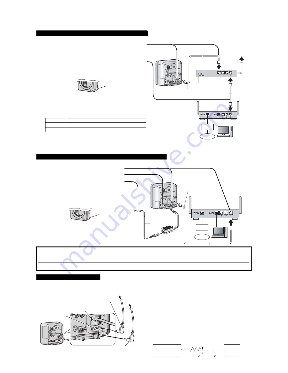
Connect the camera to your PoE hub using a LAN cable (Cat-5 straight cable) as described below.
Connect the camera to your router and to the power outlet as described below.
You can connect an external microphone and external speaker to the camera to use the Listen and Talk features, respectively. For information about these
features, see 1.2.9 Audio Features in the Operating Instructions on the CD-ROM. Connect the devices as shown below.
When connecting the camera using PoE (Power over Ethernet)
1
Connect a LAN cable to the camera and to the PoE hub.
• Your PoE hub must be connected to the router. Refer to the operating
instructions included with the PoE hub for connection instructions.
• The lens will pan and tilt when the camera is turned on.
2
Connect a LAN cable to a LAN port of the PoE hub and to a LAN port of the
router.
• Confirm that the indicator lights green after about 1 minute. If the
indicator does not light green, see 1.2 Camera Indicator Issues in the
Troubleshooting Guide on the CD-ROM.
• When the lens pans or tilts, a sound can be heard from the camera. This
is normal.
• Use a 4-pair UTP/STP cable.
• Do not use a relay connector or a hub between the camera and the PoE
hub. These devices may disturb the data or electricity transmission.
• If the PoE hub has indicators, the indicator lights as shown in the table
below.
Indicator
Description
LINK
Turns on when the data is transmitted from the camera.
PoE
Turns on when the electricity is supplied to the camera.
• If the PoE hub is turned off or power supply is temporarily cut off by the
disconnection of the LAN cable, it may take time for the PoE hub’s
indicators to light.
• The indicator display differs depending on manufacturers, refer to the
manuals of the PoE hub.
When connecting the camera using the BB-HCA3A AC Adaptor (Optional)
1
Connect the LAN cable to the camera and the router.
2
Connect the AC adaptor cord to the DC IN jack.
3
Connect the AC cord to the AC adaptor, then plug the AC
cord into the power outlet.
• The lens will pan and tilt when the camera is turned on.
• Confirm that the indicator lights green after about 1
minute. If the indicator does not light green, see 1.2
Camera Indicator Issues in the Troubleshooting Guide
on the CD-ROM.
• When you operate the camera, the power outlet should
be near the camera and easily accessible.
• Use only specified Panasonic AC adaptor (Model No.
BB-HCA3A).
• When the lens pans or tilts, a sound can be heard from
the camera. This is normal.
After the camera’s indicator turns green, you may set up the camera. Continue by following the procedure described in the
included Setup Guide.
• If the indicator does not turn green, see 1.2 Camera Indicator Issues in the Troubleshooting Guide on the included CD-ROM.
After setting up the camera according to the procedure described in the Setup Guide, read the following information.
Connecting External Audio Devices
Note
• If you use an external microphone, excessive cable length or a poor quality
cable can cause degradation in audio quality.
• The microphone cable should be no longer than 7 m (23 feet).
• Use a speaker with a built-in amplifier. The speaker connects to the camera with a
stereo audio cable similar to that used by your PC. The output signal is mono.
• Make sure the camera and speaker are turned off when connecting or
disconnecting the speaker cable, otherwise noise may be heard from the
speaker.
• The external microphone input does not correspond to a line level. Audio may
be distorted when the line level is input. Audio distortion will be solved if you
insert the following circuits. Under no circumstance should high-level audio,
such as from a speaker, be connected to this input terminal. Doing so is likely
to damage the camera.
PoE hub
PoE indicator
LINK indicator
To the power
supply
PC
Modem
Internet
LAN cable
(Cat-5 straight cable)
Router
Green
To the
power
outlet
LAN cable
(Cat-5 straight cable)
Router
PC
AC adaptor
(BB-HCA3A)
AC cord
Modem
Internet
Green
For speaker
(Output impedance
560
Ω
line level)
For microphone
(Plug-in power +3.3 V)
Microphone cable
(
φ
3.5 mm plug)
Speaker cable
(
φ
3.5 mm stereo plug)
To speaker
To microphone
Camera
Microphone Input
Audio Line
Out
Capacitor
Resistor
1 F
33 K


