background image

Stacking connector for high current 

B01

–5–

ACCTB71E  201412-T

NOTES

1. Design of PC board patterns

Conduct the recommended foot pattern design, in order to 
preserve the mechanical strength of terminal solder areas.

2. Recommended PC board and metal mask patterns

In order to reduce solder and flux rise, solder bridges and other 
issues make sure the proper levels of solder is used.
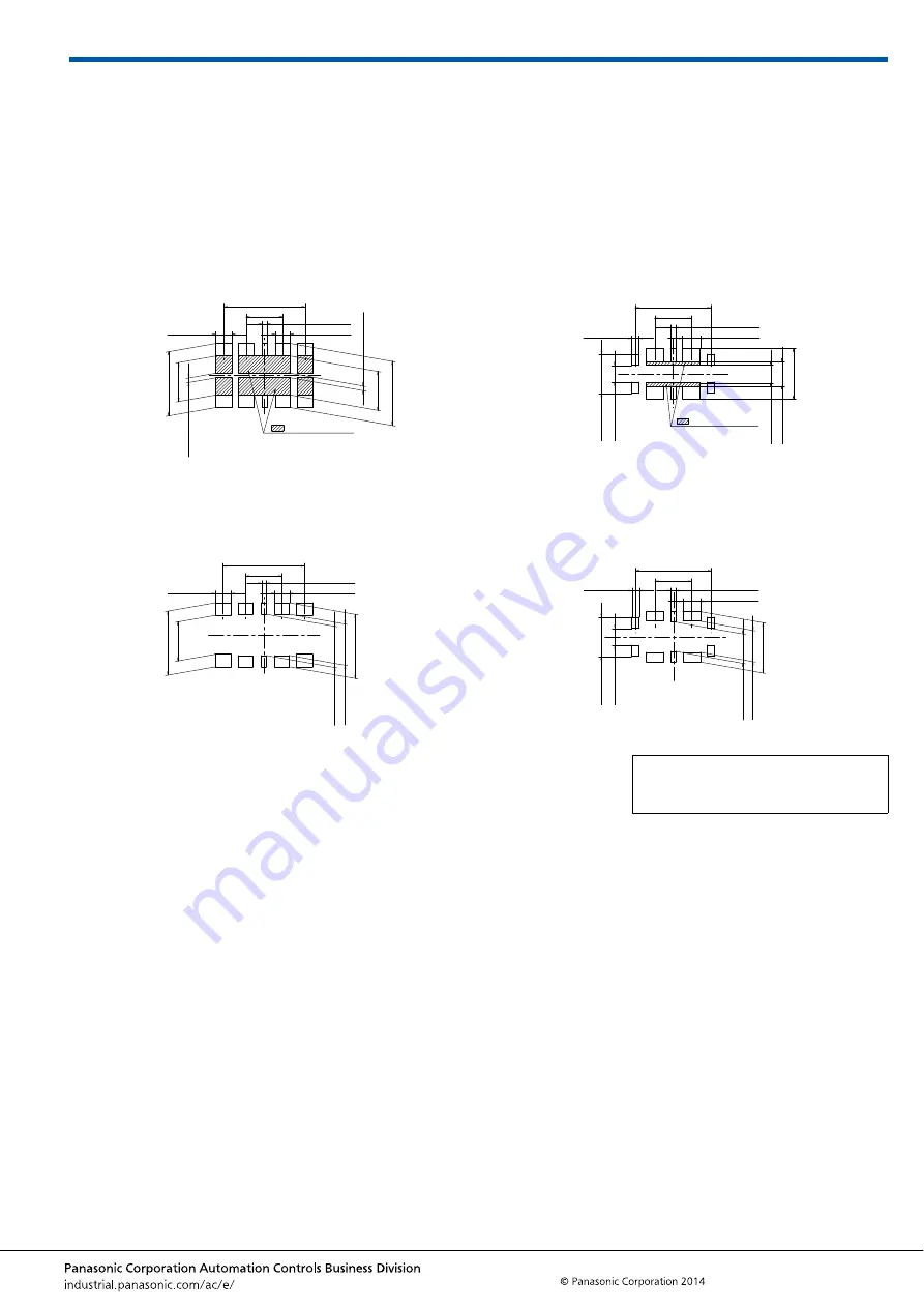
The figures to the right are recommended metal mask patterns. 
Please use them as a reference.

• Socket (Mated height: 0.6 mm and 0.8 mm)

Recommended PC board pattern (TOP VIEW)

Recommended metal mask pattern

Metal mask thickness: When 100

μ

m

(Power contact opening ratio: 88%)
(Signal contact opening ratio: 83%)

(Metal-part opening ratio: 100%)

• Header (Mated height: 0.6 mm and 0.8 mm)

Recommended PC board pattern (TOP VIEW)

Recommended metal mask pattern

Metal mask thickness: When 100

μ

m

(Power contact opening ratio: 73%)
(Signal contact opening ratio: 75%)

(Metal-part opening ratio: 100%)

: Insulation area

2.80

±

0.03

1.70

±

0.03

0.20

±

0.03

0.22

±

0.03

0.66

±

0.03

3.56

±

0.03

1.60

±

0.03

0.70

±

0.03

2.80

±

0.03

1.70

±

0.03

0.20

±

0.03

2.80

±

0.03

1.80

±

0.03

1.80

±

0.03

0.20

±

0.03

0.64

±

0.03

3.56

±

0.03

1.60

±

0.03

0.70

±

0.03

2.80

±

0.03

1.70

±

0.03

Please refer to the latest product 
specifications when designing your 
product.

: Insulation area

3.30

±

0.03

1.60

±

0.03

0.22

±

0.03

0.78

±

0.03

0.32

±

0.03

2.20

±

0.03

1.08

±

0.03

0.80

±

0.03

1.71

±

0.03

0.74

±

0.03

3.30

±

0.03

1.60

±

0.03

0.20

±

0.03

0.76

±

0.03

2.20

±

0.03

1.36

±

0.03

1.28

±

0.03

1.71

±

0.03

0.74

±

0.03

0.32

±

0.03

Содержание B01

Страница 1: ...rofile height of 0 6 mm 0 8 mm APPLICATIONS Battery section of miniature mobile devices such as smartphones wearable terminals and tablet PCs Socket Header 1 80mm 2 40mm RoHS compliant 6A 6A 3 0A 3 0A...

Страница 2: ...ity resistance Header and socket mated After 120 hours Insulation resistance Min 100M Contact resistance Power contact Max 20m Signal contact Max 90m Conformed to IEC60068 2 78 Bath temperature 40 2 C...

Страница 3: ...0 03 0 14 0 03 E 2 16 B 0 1 A General tolerance 0 2 Note 1 Because the soldering terminal Y and Z are the unified structure they are connected electrically Dimension table mm Number of pins dimension...

Страница 4: ...5 000 Specifications for taping In accordance with JIS C 0806 3 1999 However not applied to the mounting hole pitch of some connectors Specifications for the plastic reel In accordance with EIAJ ET 72...

Страница 5: ...ing ratio 88 Signal contact opening ratio 83 Metal part opening ratio 100 Header Mated height 0 6 mm and 0 8 mm Recommended PC board pattern TOP VIEW Recommended metal mask pattern Metal mask thicknes...

Страница 6: ...PC board specifications Control the thicknesses of the coverlay and adhesive to prevent poor soldering This connector has no stand off Therefore minimize the thickness of the coverlay etc so as to pre...

Страница 7: ...d then begin mounting 10 Consult us when using a screen printing thickness other than that recommended Hand soldering 1 Set the soldering iron so that the tip temperature is less than that given in th...

Страница 8: ...ors in areas of high humidity 2 Depending on the connector type the color of the connector may vary from connector to connector depending on when it is produced Some connectors may change color slight...

Страница 9: ...e connectors are delivered in 50 piece units in the condition given right Consult a sale representative for ordering sample units Condition when delivered from manufacturing Required number of product...

Отзывы: