background image

- 16 -


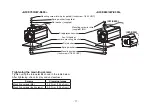
  Iris connector (IRIS)


  Input terminal for lens with an iris control function.


  Zoom/Focus connector (ZOOM/FOCUS)

(AW-E655 only)


  This connector is for the remote cable of the lens 

and is a standard input connector for lenses with 
remote functions for zooming and focusing.
When the camera is to be mounted on a Panasonic 
pan/tilt head (such as the AW-PH360/AW-PH400/ 
AW-PH405/AW-PH650), do not use this connector — 
connect the remote cable of the lens to the LENS I/F 
connector on the pan/tilt head instead.


  I/F Remote connector (I/F REMOTE)


  Input terminal dedicated to control signals from the 

optional Remote Operation Panel (ROP) (such as 
the AW-CB400) and the RCU (such as the 
AW-RC600) and the camera pan/tilt unit (such as the 
AW-PH360/AW-PH400/AW-PH405/AW-PH650).
•  AW-CB400 is connected through the optional 

connecting cable (AW-CA50T8).

•  AW-RC600 is connected through the optional RCU 

cable (AW-CA50A26).

•  Use the cable supplied with the pan/tilt head to 

connect the AW-PH360, AW-PH400, AW-PH405 or 
AW-PH650.


 Power indicator


  Red LED lamp lights to indicate that the specified 

DC power is supplied to the camera.

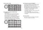
Pin No.

Signal

Pin No.

Signal

1

Return Control

7

Iris Follow

2

Not Used

8

Auto/Remote Control

3

GND

9

Not Used

4

Auto/Manual Control

10

Not Used

5

Iris Control

11

Not Used

6

Lens Power

12

Not Used

Pin No.

Signal

Pin No.

Signal

1

Focus Mode

Position/Speed/

Auto Focus

7

Signal Control

(+5.0 V)

2

Zoom Mode

Position/Speed

8

Focus Control

3

GND

9

Zoom Control

4

Iris

Remote/Camera

10

Iris Mode

Position/Speed

5

Iris Control

11

+V (+7.5 V)

6

Lens Power

12

–V (+2.5 V)

Содержание AWE350P - COLOR CAMERA

Страница 1: ...ra Model No AW E750P E655P E650P E350P Before operating this product please read the instructions carefully and save this manual for future use Installation instructions provided VQT0G71 6 FJ1003MSA06...

Страница 2: ...ECOMMENDED ACCESSORIES ONLY This class A digital apparatus complies with Canadian ICES 003 Cet appareil num rique de la classe A est conforme la norme NMB 003 du Canada For CANADA The serial number of...

Страница 3: ...NSTALLATION 10 MAJOR OPERATING CONTROLS AND THEIR FUNCTIONS 13 MOUNTING 18 FLANGE BACK ADJUSTMENT FOR ZOOM LENS 25 IRIS GAIN CONTROL IN A LENS 27 CONNECTIONS 28 ADJUSTMENT 33 USE MODE SETTING 42 MENU...

Страница 4: ...s and the camera pan tilt unit enables a wide variation of system configurations PREFACE Option cards may also be installed K The following cards are not available for AW E750 AW E655 AW E650 AW E350...

Страница 5: ...ws for adapter M4 2 AW E750 AW E655 Mounting screw for wire Inch screw 1 4 20UNC 1 Flat washer for wire Inch screw 1 Spring washer for wire Inch screw 1 AW E650 AW E350 Mounting screw for wire M4 with...

Страница 6: ...d AGC FEATURES 8 CCD readout is switchable between field and frame modes Vertical resolution can be stepped up in frame mode and it is effective for shooting still objects 9 The built in synchronized...

Страница 7: ...may result in a smeared picture unique to the CCD The ATW function under fluorescent illumination can adversely change the white balance SPECIAL NOTES ON OPERATION There is a cooling fan inside Do no...

Страница 8: ...he camera body Do not aim the camera toward the sun no matter whether it is turned on or not Do not expose the camera Remote Control Unit RCU or other units to rain or moisture and do not try to opera...

Страница 9: ...r any servicing to qualified service personnel Handle the camera with care Protect the precision made lens by placing the lens cap over when the camera is not in use If the lens is not installed prote...

Страница 10: ...t temperature 10 C to 45 C 14 F to 113 F range p Locations near the air outlet of an air conditioner or near a door where the camera will be exposed to incoming outside air or other locations where th...

Страница 11: ...s M4 1 5 N m 15 kgf cm Mounting screws Inch screws 2 0 N m 20 kgf cm Mounting screw for wire supplied Inch screw 1 4 20UNC Mounting screw for wire supplied M4 Drop prevention wire Pan tilt head or cam...

Страница 12: ...ounting bracket Mounting screws M6 for installation end wire At the installation location be absolutely sure to use the anchor bolts and ensure that the strength of the installation surface is at leas...

Страница 13: ...4 20UNC Depth 10 mm 3 8 Front View Side View 17 5 mm 11 16 10 mm 3 8 Mounting screws Inch screws 1 4 20UNC Depth 10 mm 3 8 Mounting screws Inch screws 1 4 20UNC Depth 10 mm 3 8 Use the adapter mounti...

Страница 14: ...le AW E750 AW E655 only To install the camera on a wall or ceiling or to use a pan tilt head or tripod secure the unit using this screw hole 1 4 20UNC or using the accessory mounting adapter Furthermo...

Страница 15: ...h is pressed while the Main Menu is on the screen While the Sub Menu is displayed any setting can be brought up to a higher value with this switch When the menu is not displayed or the camera is in sh...

Страница 16: ...600 and the camera pan tilt unit such as the AW PH360 AW PH400 AW PH405 AW PH650 AW CB400 is connected through the optional connecting cable AW CA50T8 AW RC600 is connected through the optional RCU ca...

Страница 17: ...amera is to be synchronized with the reference signal BB Cable clamp Clamp the DC cable with 6 5 plug connected to the DC 12 V Input connector to prevent it from slipping out Optional card slot Slot f...

Страница 18: ...ed to be attached in a different way Therefore reference should also be made to the operating instructions that accompany the lens Remove the lens mount cap align the lens with the thread ridges on th...

Страница 19: ...in the camera mounting screw hole Inch screw 1 4 20UNC of the attached camera mounting adapter Camera mounting adapter For use in a very bright location paste the supplied round seal on the hole not u...

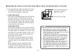
Страница 20: ...lt head When the unit is to be mounted onto a tripod camera mounting bracket or other part refer to pages 10 to 12 and provide your own drop prevention wire mounting screws and washers w Mounting the...

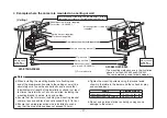
Страница 21: ...20UNC Notes p When installing the mounting bracket or attaching one end of the drop prevention wire to the ceiling or a wall be absolutely sure to use the anchor bolts and ensure that the withdrawal s...

Страница 22: ...he mounting bracket or attaching one end of the drop prevention wire to the ceiling or a wall be absolutely sure to use the anchor bolts and ensure that the withdrawal strength of the installation sur...

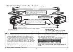
Страница 23: ...sure to use the anchor bolts and ensure that the withdrawal strength of the installation surface is at least ten times the total mass of all units installed including the mounting bracket camera lens...

Страница 24: ...prevention wire to the ceiling or a wall be absolutely sure to use the anchor bolts and ensure that the withdrawal strength of the installation surface is at least ten times the total mass of all uni...

Страница 25: ...2 meters away from the camera 4 Set the lens to its TELE end first and adjust its focus with the focus ring 5 Set the lens to its widest angle next and adjust its focus with the flange back adjust ri...

Страница 26: ...object 2 Aim the camera at any object over 2 meters away from the camera remove the cap over the camera s flange back adjust screw and loosen the LOCK screw 3 Set the lens to its TELE end first and ad...

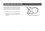
Страница 27: ...river through the hole may be done as follows Shape and location of the hole may vary depending on the type of lens 1 Turn the iris selection switch to Position A AUTO 2 Rotate the iris gain control t...

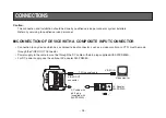
Страница 28: ...TOR Connection to any device which has a composite input connector such as a video monitor or a VTR must be made through the VIDEO OUT Connector Power supply to the camera must be through the DC cable...

Страница 29: ...Turn RCU power on and the power indicator lamp will light The camera can now be remote controlled by the RCU Notes The maximum extension distance between the camera and AW RC600 is 100 m Use the follo...

Страница 30: ...r of the connecting cable to I F REMOTE connector of the camera The 10BASE T cable must be connected to the ROP 3 Turn the OPERATE switch of ROP to ON and the camera can be controlled remotely by the...

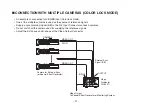
Страница 31: ...ing signal BB to the G L Input Connectors of each cameras Do not switch off the camera used for supplying the reference signals Adjust the SC phase and H phase at the Video Output Connector VIDEO OUT...

Страница 32: ...oftware used to control the camera DC cable with 6 5 plug supplied with AW PS505A Computer VIDEO OUT Connector AC Adapter AW PS505A 75 j Coaxial Cable Composite Video Input Connector VIDEO IN Video Mo...

Страница 33: ...o readjust the camera to the ambient conditions The preset conditions will be renewed whenever you input new conditions 1 Turn the white balance selection switch to either AWC A or AWC B or select the...

Страница 34: ...g of the object is too weak Since the camera has a built in memory the set white balance will remain in the memory even if power is turned off Therefore it is not necessary to reset the white balance...

Страница 35: ...the monitor screen appears pure white Use an oscilloscope or a waveform monitor for precise adjustment For details on the menu operations using the multi hybrid control panel refer to the Operating I...

Страница 36: ...estal blue pedestal setting after setting the black balance ADJUSTMENT with the RCU ROP or multi hybrid control panel In the case of the RCU set the auto white auto black selector switch to the ABC po...

Страница 37: ...s 2 Select Pedestal item in the brightness setting Sub Menu Select Pedestal in the Iris Shutter Gain Set sub menu in USER MODE 3 Set the pedestal level to 5 IRE 0 035 V with the YES ABC switch or the...

Страница 38: ...signals by adjusting them with the horizontal phase control of the camera RCU ROP or multi hybrid control panel ADJUSTMENT by CAMERA or multi hybrid control panel 1 Press the NO BAR switch for over 5...

Страница 39: ...TTING menu 4 Push the CONT dial straight down and display H PHASE on the bottom line of the LCD 5 Observe the waveforms of the genlock signal black burst signal or video signal VBS and video signal ou...

Страница 40: ...nt with the YES ABC switch and the NO BAR switch For details on the menu operations using the multi hybrid control panel refer to the Operating Instructions of the multi hybrid control panel ADJUSTMEN...

Страница 41: ...rrier phase can now be adjusted finely by turning the CONT dial 5 Keep adjusting the SC COARSE and SC FINE phase so that the sub carrier color phase of the video signal output is aligned with the colo...

Страница 42: ...functions for four use modes have been preset Functions can be set as best suited to each use mode Halogen mode Suited to indoor shooting such as at weddings parties lecture meetings events etc Settin...

Страница 43: ...switch or SCENE FILE button CAMERA ITEM AWC YES ABC NO BAR MENU Remote control unit Scene file switch Multi hybrid control panel SCENE FILE button Remote operation panel SCENE FILE button Operation m...

Страница 44: ...enu of Halogen Fluorescent Outdoor Mode Main Menu of User Mode Use Mode Blinking Notes Composite signals are output from the video output regardless of the position of the RCU menu ON OFF switch End i...

Страница 45: ...ired item to be changed in its settings using the the MENU switch and ITEM AWC switch 5 Press the YES ABC switch or NO BAR switch to change the settings 6 Select Return using the MENU switch and ITEM...

Страница 46: ...o return to the initial settings refer to page 70 wSUB MENU Halogen Mode Fluorescent Mode Outdoor Mode Color Set Display Sharpness DTL Set Display Other Set Display G L Adjustment Set Display Brightne...

Страница 47: ...ns of the screen are excluded from measurement Top cut About one third of the top part of the screen is excluded from measurement BTM cut About one third of the bottom portion of the screen is exclude...

Страница 48: ...only when the Auto Gain Up control 5 is in the OFF position 0 dB 0 dB should be selected in normal cases 1 dB to 30 dB Use this range if sufficient video output cannot be obtained even when the lens...

Страница 49: ...ollowed by ALC AGC and then by the data storage in this order and the light quantity is automatically adjusted The electronic shutter setting 2 cannot be changed OFF Under normal circumstances this se...

Страница 50: ...in if you simply select AWC A or AWC B provided that the camera is used under the same conditions Fine color adjustment can be made after setting AWC by red blue gain adjustment in user mode or from t...

Страница 51: ...Select Sharpness Super DTL If contour correction is not sufficient at the Sharpness position when Detail Level setting is set to LOW or HIGH select the Super DTL position 2 Detail Level Setting Level...

Страница 52: ...2 Electronic Shutter Setting Shutter Speed OFF 1 100 to 1 10 000 S Scan Auto ND OFF Electronic shutter is turned off 1 100 1 250 1 500 1 1 000 1 2 000 1 4 000 1 10 000 Electronic shutter operates at...

Страница 53: ...the computer 6 Component Output Setting Component RGB Y Pr Pb Y C This enables RGB Y Pr Pb or Y C to be selected as the component signals which are to be output from the I F REMOTE connector 7 Digita...

Страница 54: ...ugh Normal 1 16ND 1 64ND model AW E655 only IR Through The infrared shooting mode is established Irradiate the subject with infrared light Normal Under normal circumstances this setting is used 1 16ND...

Страница 55: ...be set with the RCU switch or VR in RCU mode To return to the initial settings refer to page 70 Color Set Display Detail Set Display G L Adjustment Set Display Iris Shutter Gain Set Display 1 2 3 4 5...

Страница 56: ...56 Color Matrix Set Display Other Set Display 1 2 3 4 5 6 7 8 9 10 11 12 13 14 15...

Страница 57: ...About one third of the top portion of the screen is excluded from measurement BTM cut About one third of the bottom portion of the screen is excluded from measurement R L cut About one third of both...

Страница 58: ...Scan has been selected as the electronic shutter mode setting 5 When the screen of a work station etc is to be shot the noise on the horizontal bars can be reduced by proceeding with the synchro scan...

Страница 59: ...e Use this setting if it is not possible to achieve a satisfactory video output even at 30 dB Only 0 dB 9 dB or 18 dB AGC LOW AGC HIGH can be selected in case of using the RCU If the lens iris switch...

Страница 60: ...e CCD storage time OFF Under normal circumstances this setting is used Auto ALC is performed followed by AGC and then by the data storage and the camera automatically adjusts the light quantity If the...

Страница 61: ...n adjustment controls R B GAIN dials from the RCU ROP P SET 3 200K The white balance is adjusted to 3 200K illumination P SET 5 600K The white balance is adjusted to 5 600K illumination 3 ATW Speed Se...

Страница 62: ...urns to 0 after ABC setting in using the camera alone 6 Negative Positive Selection Nega Posi Posi Nega Posi Normal image Nega Image is shown reversed in darkness and color K The negative images can b...

Страница 63: ...High Contour correction quantity can be selected Detail settings made using the Horizontal Vertical Detail Level HIGH LOW Setting 2 Horizontal Detail Level HIGH Setting H Detail Level H L 1 to 63 3 Ve...

Страница 64: ...f the darker portions of an object can be emphasized This setting is possible only when the Level Dependent Compensation Level Setting 9 is set to 0 10 Chroma Detail Compensation Level Setting Chroma...

Страница 65: ...ncreases or decreases the intermediate color of yellow Yl Phase Varies the hue of the yellow Yl_G Gain Increases or decreases the intermediate color between yellow and green Yl_G Phase Varies the hue...

Страница 66: ...the suppression of black portions at low luminance can be set to ON or OFF 6 Clean DNR Setting Clean DNR HIGH LOW OFF This enables the clean DNR effect to be selected 7 3D DNR Setting 3D DNR OFF Low...

Страница 67: ...the fan starts operating when the temperature exceeds approx 10 C 50 F in the storage mode or approx 35 C 95 F in any other mode Under normal circumstances the Auto setting is used 14 Auto Focus Sett...

Страница 68: ...ZOOM FOCUS connector has been inserted in the model AW E650 1 Zebra Indicator Setting Zebra Indicator ON OFF This is used to select whether to display the zebra pattern on the viewfinder ON The zebra...

Страница 69: ...ositions and as such they may be at variance with their optical positions The inside and outside frames denote safety zones of about 90 and about 95 respectively 4 EVF Output Setting EVF Output Y CVBS...

Страница 70: ...tch within about 10 seconds to return to the initial settings the existing settings are initialized the screen shown at and the camera returns to main menu 3 If the NO BAR switch is pressed or if the...

Страница 71: ...0dB 0dB OFF 0 0 0 Top cut OFF OFF 0dB 0dB OFF 0 0 0 Top cut ON ON N Eye H 1 N Eye 2 OFF 40 Color Set Chroma Level Flesh Tone White Bal ATW Speed Nega Posi 0 0 AWC A Posi 0 0 AWC A Posi 0 0 ATW Mid Pos...

Страница 72: ...OFF Normal Mid Auto ND Normal 9600bps Y Pr Pb OFF Auto OFF Normal O User Mode Item User mode Iris Shutter Gain Set Picture Level Light PEAK AVG Light Area Auto Iris Adjust Shutter Mode Step Synchro Ga...

Страница 73: ...in Mg_R Phase R Gain R Phase 0 0 27 0 0 0 15 0 Color Matrix Set 2 R_Yl Gain R_Yl Phase Yl Gain Yl Phase Yl_G Gain Yl_G Phase G Gain G Phase 0 0 18 6 0 0 30 112 Item User mode Color Matrix Set 3 G_Cy G...

Страница 74: ...74 18 11 16 77 3 1 32 10 25 64 34 15 16 84 3 5 16 12 15 32 170 6 11 16 10 25 64 AW E750 APPEARANCE Unit mm inch...

Страница 75: ...75 MIC 96 3 3 4 34 15 16 10 25 64 18 11 16 84 3 5 16 12 15 32 160 6 5 16 10 25 64 Unit mm inch AW E655...

Страница 76: ...76 Convertible Camera AW 77 3 1 32 34 15 16 10 25 64 84 3 5 16 12 15 32 155 6 1 8 10 25 64 Unit mm inch AW E650...

Страница 77: ...77 FOCUS LOCK 34 15 16 77 3 1 32 10 25 64 84 3 5 16 1 3 64 145 5 11 16 10 25 64 AW E350 Unit mm inch...

Страница 78: ...p 75 ohms C 0 286 V p p 75 ohms burst D sub 50P M 1 Y Pr Pb Y 1 V p p 75 ohms Pr Pb 0 7 V p p 75 ohms D sub 50PM 1 RGB G 1 V p p 75 ohms RB 0 7 V p p 75 ohms D sub 50P M 1 Standard illumination color...

Страница 79: ...t output connectors VIDEO OUT BNC connector G L IN BNC connector IRIS 12P round connector DC 12 V IN DC connector I F REMOTE 50P D sub connector VIDEO OUT BNC connector G L IN BNC connector IRIS 12P r...

Страница 80: ...5 ohms D sub 50PM 1 RGB G 1 V p p 75 ohms RB 0 7 V p p 75 ohms D sub 50P M 1 Standard illumination color temperature 2 000 lx F14 3 200K 2 000 lx F9 5 3 200K Minimum illumination 0 00005 lx at F1 4 Ni...

Страница 81: ...d Input output connectors VIDEO OUT BNC connector G L IN BNC connector IRIS 12P round connector DC 12 V IN DC connector I F REMOTE 50P D sub connector Indicator Red LED power ON when lighted Allowable...

Страница 82: ...Memo...

Страница 83: ...Memo...

Страница 84: ...Web Site http panasonic net Panasonic Corporation 2011...

Отзывы: