background image

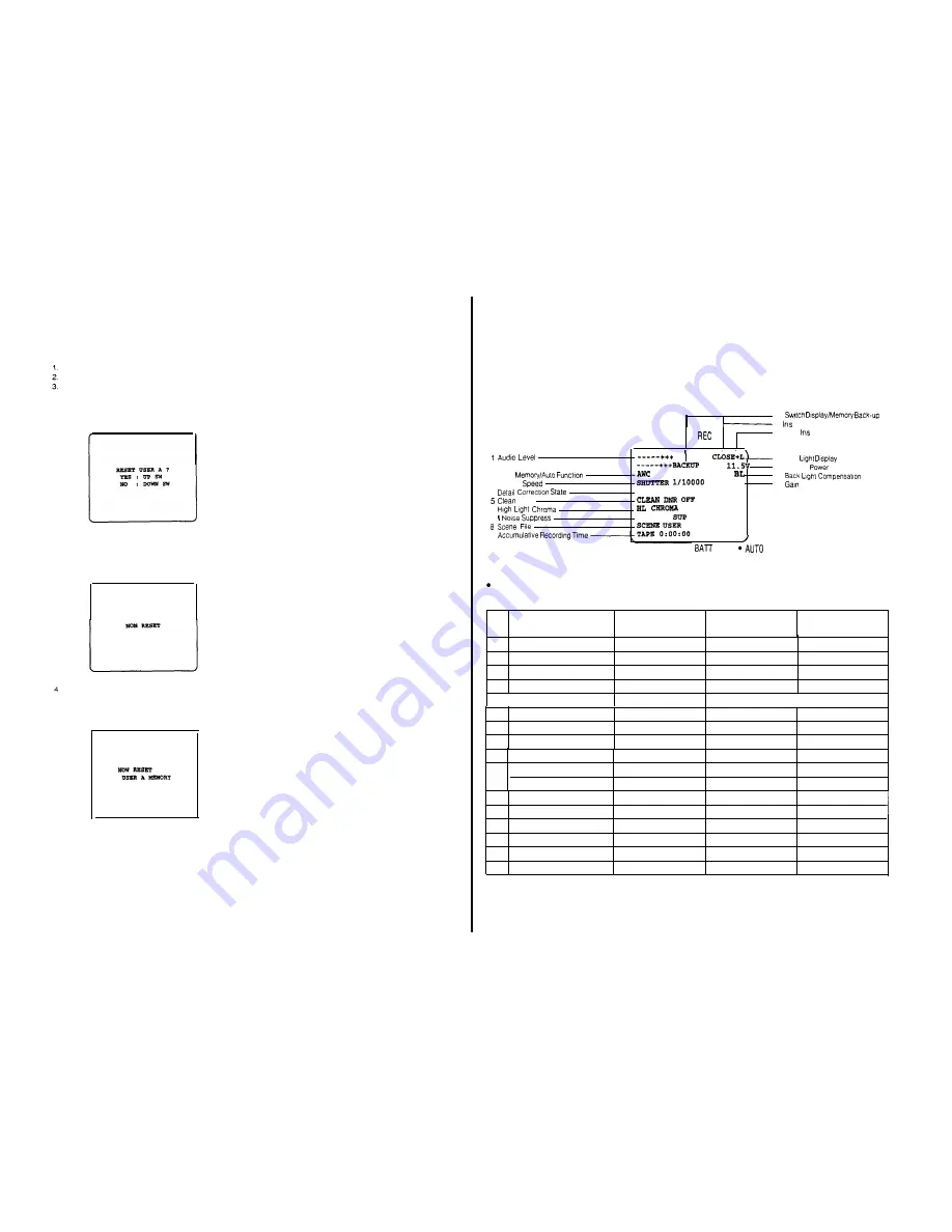
Reset of the setting data

To  reset the  menus to  the  condition  preset  at the  factory,

a  reset functlon is provided   wih this camera

How to Reset

Select  menu  to  reset.
Tun  off  the power of the camera once

Turn  on the power of  the camera  while  pressing  the

Page Switch (13) of the camera

The  following reset  screen  is displayed in the viewfind-

er or monitor

Note: To cancel the  reset,  press  the  Down  Switch

before  pressing  Up  Switch

When  the  Down  or Up  Switch  is  not pressed, the  reset

is canceled  aufomatically

Press the Up Switch (15)
The  following  display  is indicated and  the  setting   con-

dltions  is reset.

-  66  -

CHARACTER DISPLAY

The  following  operatlon  & warning displays are shown in the viewfinder to show the  Operating  conditions of the camera

Notes:

1. The  displays of the  viewflnder  are not recorded.

2

The  displays  are  not shown while a playback picture is on the  viewfinder screen

* Display Positions

10 


 ll 

 Number

??

12 Auto 

AUDI0

TALLY


 13 Low 


  N G  

14 Camera 

2 AWC 


A

15 


3 Shutter 


0 DB

16 

 Up


DETAIL RIGH


 DNR


 OFF

7   


1 NOISE 


OFF


A


??

SHTR

??

H.G.

 Timing of Displays

The  viewfinder  displays appear in the  viewfinder  as stated  below:

NO

Display

Displayed  all the tlme

Displayed  in short intervals
only when the condition

Displayed only when the

changes

Check Button (25) is pressed

1

Audlo Level

0

x

0

2

AWC  Memory/Auto  Functlon

x

0

0

3

Shutter Speed

x

0

3

4

Detall Correct8on State

x

0

0

1

5  /  Clean DNA

I

I

1

x

0

0

6

High Light Chroma

x

0

0

7

I  Noise Suppress

x

0

0

8

Scene  File

x

0

c

9

Accumulative Recording Time                                  X                                                  X                                                  0

Switch   Display                                                            x                                                   0                                                  0

10  -

Memory Back-up                                                       *0                                                   x                                                  0

11

lris Number

0

x

0

12  I Auto  Iris

0

x

I                                                                                0

13

Low  Light Dlsplay

0

x

3

14

Camera  Power

 0

x

5

15

Back  Light Compensation

0

x

 0

16

Gain  Up

x

0                                                    0

*  Thls  display  appears  only when the  memory  back-up  battery has  any  failure

 - 67 - 

Содержание AW-F575E

Страница 1: ...Electric Industrial Co Ltd PO Box 288 Osaka 530 8691 Japan Colour Video Camera AW F575E ...

Страница 2: ...ight 101 on the viewfinder also lights When this button is pressed once more the recorder is set to the Pause mode Recording Pause and the Recording Tally Indicator and Tally Light will go off 7 6 Auto White Auto Black Set Switch AUTO W B BAL AWC HOLD ABC This switch sets the white balance and black balance automatically as follows AWC This position is used for setting the white bal ance when the ...

Страница 3: ...or on the monitor 14 Item I Noise Suppress Switch ITEM I NS When the User Set Switch is set to the position 1 or 2 this switch is used to move the cursor to the various items in the menu When the User Set Switch is set to the OFF position the I Noise Suppress in the menu can be selected by this switch Note Noise of the I axis on the vector can be sup pressed when the Detail Level Selection Switch ...

Страница 4: ...Caution if the incorrect filter is selected the Automatic White Balance Setting may not be suc cessfully completed 32 Viewfinder Lock Lever The wiewfinder s position is locked or released through the use ot this lever When the lever is released the viwefinder can be slid approximately 45 mm 1 3 4 laterally and 20 mm 13 16 back and forth Be sure to lock the lever after having adjusted the viewfinde...

Страница 5: ...using this switch the desired power source con nected to the camera can be selected BATT EXT DC This position is used for power supply from the battery pack and external DC source or through an AC adaptor VTR RCU This position is used when power is to be supplied through the 26 pin connector from the VTR or the Remote Control Unit RCU 55 Audio Level Selection Switch AUDI0 LEVEL 20 60 dB Two audio ...

Страница 6: ...onitored INT The sound plcked up by the microphone can be monitored PB The played back audio can be monitored Note The camera has been preset to the INT position at the factory 72 Audio Level Selection Switch AUDI0 LEVEL 20 60 dB Two audio output levels lo the VTR can be selected 20 dB or 60 dB The camera has been preset to 20 dB at the factory When using this adaptor with WVRC700A set this switch...

Страница 7: ... Generator is supplied to the auxiliary connector of the Remote Control Unit RCU while the camera is set up for system operatlon this signal can be previewed on the electronic viewfinder as long as this button is kept pressed When a 3 4 U vision portable recorder connected through the VTR s 14 pin camera input connector or an S VHS VTR recorder is set to the playback mode the played back picture c...

Страница 8: ...n the high gain selection of N E has been selected by the Colour Bar Night Eye Camera Selectlon Switch 27 106 Brightness Control BRIGHT Turn this control clockwise to increase the brightness of the picture in the wiewfinder 107 Contrast Control CONTRAST Turn this control clockwise to increase the contrast of the picture in the viewfinder 108 Peaking Control PEAKING When shooting under low light co...

Страница 9: ...ghts Note While the black balance adjustment is being performed the picture will flash in the vlewfinder and on the monitor screen This flashing indicates that the adjustment is currently being performed and will cease once the adjustment is completed 128 Lens Iris Selection Switch IRIS M A AUTO This switch is used to set the lens iris of the auto iris servo control zoom lens as follows AUTO The i...

Страница 10: ...sition at the factory This connector is used to input the gen lock signal to the Remote Control Box when using the Remote 146 Video Output Connectors Control Box extended trom the Remote Control Unit OUTPUT VIDEO 1 VIDEO 2 These connectors supply a composite video signal to 156 Remote Control Unit Extension Connector a Special Effects Generator a Video Monitor or a VTR This connector is used to ex...

Страница 11: ...t It goes out once the white and black balances have been correctly set This indicator lights when the white or black balance is set improperly In this case carry out the automatic setting procedure for white and or black balance 180 White Balance Selection Switch AUTO ATW ATW A B This switch is used to select the white balance mode as follows ATW The white balance can be adjusted automatical ly A...

Страница 12: ... 2 Use for cable length of 75 150m 225 450 ft 3 Use for cable length of 150 230m 450 690 ft 4 Use for cable length of 230 300m 690 900 ft 199 Subcarrier Phase Fine Control for Gen lock SC FINE This control allows for adjustment of the camera signal subcarrier phase from 0º to 360º to match the phase with that of the burst signal at the Gen lock Input Connector in a system configuration 197 Subcarr...

Страница 13: ...cator shows the camera operator that recording is in progress and the recording signal is being sent to the line output 218 5 Viewfinder Mounting Bracket WV 071 This is used to mount the 5 Electronlc Viewfinder WV VF65B on the AW F575E Colour Camera See page 34 for installation details LENS CONTROL KIT WV LK35 221 Clamper Install the zoom controller on the right tripod arm by using this clamper 22...

Страница 14: ...41 Release Button The Lock Levar 242 can be unlocked by presslng this button 242 Lock Lever The mounting or removing of the camera from the Tripod Mounting Adaptor WV OT700 is made by lock ing or unlocking this lever 243 Mountlng Holes These holes are used to mount the Tripod Mounting Adaptor on the tripod CARRYING CASE WV CC500A 251 Cushion 1 for AW AD500AE Thls cushion is used to contaln the ENG...

Страница 15: ... 2 1 Remove the Body Cap from the camera 2 2 Attach the 14X Auto Iris Servo Control Zoom Lens into the Lens M o u n t Hole a n d turn t h e Lens H o l d Ring Knob 30 clockwlse to secure the lens to the camera body 2 3 Check to make sure that the lens is mounted securely 2 4 Connect the Lens Cable ta the 12 pin Lens Connector 1 on the camera 32 3 4 Mount the Optlonal Microphone Holder on this camer...

Страница 16: ...der Connect the viewfinder angle Note When connectlng the viewfinder cable of the viewfinder to the viewfinder connector on the camera Use the viewfinder connector conversion cable supplied in between the two After connection is completed attach the conver sion cable to the top cover of the camera by turn ning the wing screw 34 tevhder Connector Conversion Cable 6 Mounting of the MII Format VTR AU...

Страница 17: ...R with two screws which come with the VTR 36 8 Installation of the AC Adaptor Charger WV PS34 When the AC Adaptor Charger WV PS34 is used with the ENG EFP Colour Camera as an AC Adaptor this installation procedure should be followed 8 1 lnstall t h e AC Adaptor Charger on t h e rear of the c a m e r a b y matching t h e recesses in t h e AC Adaptor Charger with the rails on the camera and then sli...

Страница 18: ...ra on the Tripod Mountlng Adaptor While pressing the Release Button 241 on the Lock Lever 242 of the Tripod Mounting Adaptor unlock the lock lever by turning it counterclockwise as shown in the Illustration 10 3 Place the camera on the Tripod Mounting Adaptor and make sure the protusion at the rear of the cam era is properly engage wth the slot at the rear of the Tripod Mounting Adaptor 38 10 4 Tu...

Страница 19: ...ox Connector Notes 1 Only video slgnal audio signal 2 0 dB a n d start stop signal are sent to the sub VTR 2 The extension cable length for the sub VTR is up to 10m 30 ft 3 In the above system connectlon the video signal from the Monitor Output Connec or 36 on the Camera Head takes priority over the vldeo sIgnaI from the Monttor Output Conector 154 on the Remote Control Box So the picture is not d...

Страница 20: ... be bridged or looped through to another RCU Connect the coaxial cable for the lineview signal between the effect output connector on the production system and the Auxiliary Input Connector 144 or 204 on the RCU The signal may be bridged or looped through to another RCU Notes 1 The Tally light and Intercom between the camera RCU and Speclal Effects Generator will function only when the 4 pin cable...

Страница 21: ...owing items are not available a Bidirectional Inter Communication b Audio Output c Zoom or Focus Control d Pan Tilt Control 7 Pan Tilt Control SIgnaI Input to the Control Connector on the RCU is output from Control Connector on AW AD700BSE 8 For the Audio function set the Switch 2 on the MOD board Inside this unit as shown below 44 OPERATINGPROCEDURE FOR CAMERA RECORDER APPLICATION 1 T u r n on th...

Страница 22: ...ic Shutter On Off Switch 11 to select the appropriate shutter speed 1 1 The camera s condition may be confirmed by pressing the Check Button 25 while a normal picture is being vlewed Refer to Character Dlsplay on page 67 for details 12 Aim the camera at the scene to be recorded and adjust the focus and zoom of the lens accordingly 13 Press the VTR Start Stop Button 92 on the lens or 5 on the camer...

Страница 23: ... VTRs with a C a m e r a Select switch such as Panasonic VTR AG 6400 Set the Camera Select swich on the VTR to NOR MAL positlon AWC 0 N O R M A L 9 Set the whlte balance as follows S e t t h e White B a l a n c e Selection Switch 2 8 to t h e AWC A or AWC B position While aiming the c a m e r a at a white object e g white paper or a whlte Wall set the Auto Whlte Auto Black S e t Switch 6 to t h e ...

Страница 24: ...ressing it down The lens iris is automattcally closed and the black balance is set automatlcally Whle the black balance has been set the lens iris autocally returns to its previous position The Auto Warning indicator blinks while the black balance is being set and it goes off when the black balance has been correctly set While the black balance is being set ABC also blinks in the viewfind et scree...

Страница 25: ...the colour bars from the camera are similar to the colours of the colour bars generated by the Special Effects Generator 10 Set the white balance as follows Set the White Balance Selection Switch 126 on the RCU to the AWC A or AWC B position While aimig the camera at a white obfect e g a white paper or a white wall set the Auto Whlte Auto Set Swich 127 or 178 on the RCU to the A posi tion momentar...

Страница 26: ...should be done before operation Refer to page 17 for the details Automatic iris adjustment when lens is changed Turn power on while pressing the item ITEM AWC switch The lens iris is automatically opened and closed for auto matic iris adjustment It will be completed in around 30 seconds ADJUSTMENT Gen lock Adjustment When using one or more cameras in a system which includes a special effect genera...

Страница 27: ...nder and ABC OK appears when the black balance has been correctly set This Indication disappears after a few seconds If the Auto Warning indicators remain lit and ABC NG appears in the viewfinder screen the black balance adjustment should be carried out once more The black balance setting will be kept in the memory for approxlmately 10 years even If the power of the camera is turned off It is reco...

Страница 28: ...e settings have been stored in the memones moving between two light sources is easily accomplished by sim ply changing the White Balance Selection Switch 28 on the camera or 126 or 180 on the RCU to the position matching the light source Recording is not interrupted when the white bal ance memory isswitched 4 If the camera has not been used for a long period of time the white balance as well as th...

Страница 29: ...he Page Switch 13 of the camera or 136 191 of the RCU RCB the Main Menu can be displayed in the viewfinder or on the monitor screen 4 By pressing the Item Switch 14 of the camera or 135 190 of RCU RCB the cursor is moved to the various Items in the menu The item identified by the cursor can have its level set or changed at this point 5 Change of the mode or level is made by use of the Up 15 Down 1...

Страница 30: ...asurement 7 CLEAN DNR OFF LOW HI Clean DNR Digital Noise Reduction Switch The SIN ratio on the screen can be improved by thls switch Note When the camera is operating alone this func tion can be made by the DNR Switch inside the camera In this case the display in the menu shows the set siwtch condition 8 LIGHTING HALOGEN FLUORESCENT OUTOOOR Lighting Selection Only Scene 2 HALOGEN Thls position is ...

Страница 31: ...k mode can be adjusted fine 31 NOISE SUP OFF LOW HI Signal Suppression On Off Setting Noise of the I axis on the vector can be suppressed 32 CORNER DTL ON OFF Corner Detail On Off Setting By setting to the ON positlon the comer detail of plc ture is improved when the Detail Level Selection Switch 20 is set to the LOW or HIGH position 33 PRECISION DTL ON OFF Precision Detail On Off Setting When set...

Страница 32: ...t recorded 2 The displays are not shown while a playback picture is on the viewfinder screen Display Positions 10 ll Number 12 Auto AUDI0 TALLY 13 Low N G 14 Camera 2 AWC A 15 3 Shutter 0 DB 16 Up 4 DETAIL RIGH DNR 6 OFF 7 1 NOISE OFF A 9 SHTR H G Timing of Displays The viewfinder displays appear in the viewfinder as stated below NO Display Displayed all the tlme Displayed in short intervals only ...

Страница 33: ...sitlon Display Display Time Auto Warning Indicator Cause Remedy l HIGH LIGHT 2 seconds ON Excessive britght Iight Reduce Iighting on object or reduce lens iris Reset the white balance AWCPSET 2 seconds ON White Balance Selection Switch is set to PRESET Set this switch to AWC A or AWC B LOW LIGHT 2 seconds ON Insufficient Light Prepare an additional Iight source Reset the white balance AWC NG 2 sec...

Страница 34: ...oise Suppress Display The I Noise Suppress state is displayed for one sec ond when the item Noise Suppress Switch is pressed in the menu off mode Note These selections can be made by the menu Display Positlon of Item Noise Suppress Switch 1 NOISE SUP OFF OFF Note The above displays are indicated by pressing the Check Button 25 6 Scene File Display The scene file setting is changed or Check Button ...

Страница 35: ...Dlsplay Description None The peak level of incoming Iight generates 40 IRE or more L The peak level of incoming Iight generates 40 IRE or less 14 Camera Power and Anton Bauer Intelligent Digital Battery The voltage level supplied to the camera from the Battery Pack AC Adaptor Charger or VTR is dis played 13v OFF Approx OFF Approx 12V OFF Approx OFF Approx OFF Approx 8V OFF Approx 10 Note If BATT i...

Страница 36: ...WC position If the Check Button is kept pressed the camera will not be shifted to the time setting mode 74 7 Press the Recording Time Reset Button 21 to change the Day ID SETTING 8 After setting the correct Day press the Check Button 25 9 For setting the Year and Hour follow the same pro cedure used for the Month or Day 10 For Setting the Minute press the Check Button 25 after setting the Hour The...

Страница 37: ... 4000 s 1 10000 s synchro scan ELC 3200K 5600K with 6 25 ND 5600K 26 pin Studio Cable Max 300m Power Colour Bar N E Camera Selectoon Hogh Gaon Selectoon Whote Balance Selection Auto White Auto Black Set Level Indicator Zone VTR Start Stop Check Lens iris Selection Detaill Level Selection High light CHROMA Recording Time Reset Electronic Shutter On Off Back Light Comp Scene File Selection Page Item...

Страница 38: ...nder WVVF65B Remote Control Unlt RCU WV RC700A WV RC550 Remote Control Box RCB WVCB7OOA OTHER OPTIONAL ACCESSORIES VTR Cable WV CA26A14 26P 14P 3m 10 ft WV CA26A26 26P 26P 3 m 10 ft Joint Connector WV CA26T26 26 32 Conversion Cable WV CA26T32 32 26 Conversion Cable WV CA32T26 Studio Cable WV CA26U15 15m WV CA26U30 30 m WV CA26U100 1OOm RCB Cable WV CA10B2 2 m WV CA10825 25 m WV CA10B50 50 m Gun ty...

Отзывы: