INF-1
1. SOFTWARE VERSION UPGRADE METHOD
1.
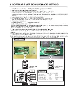
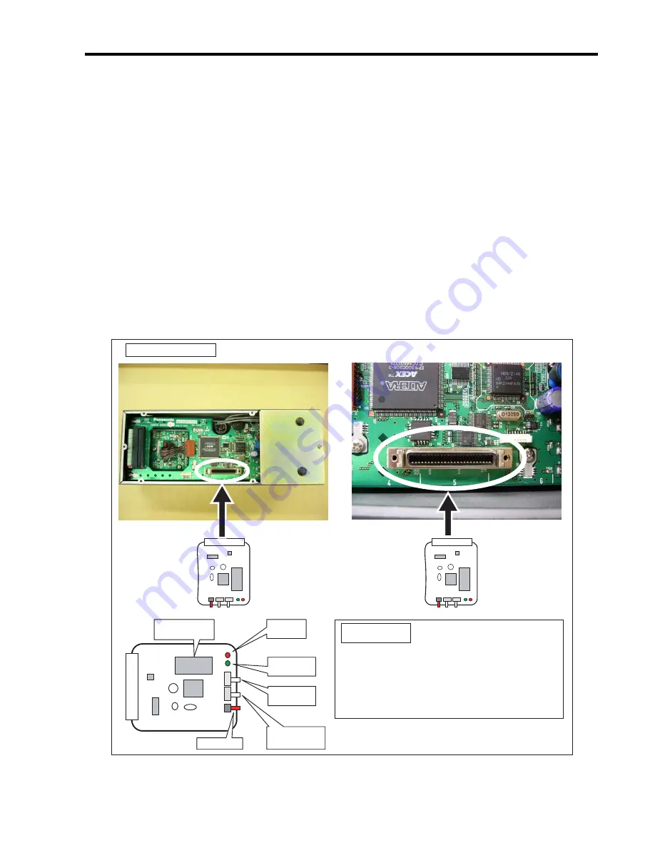
Install the new version software (ROM) on the ROM changer board (VFK1667).
2.
Make sure that the power of the unit is turned OFF.
3.
Connect the board to the P5 (50 pin) connecter of Main PCB as shown in the figure.
4.
Set the Baud Rate switch on the ROM changer board to the center position.
Since write protection is not activated, write operation can be started regardless of WRITE/PROTECT
selection.
5.
Turn on power of unit. Then the green LED on the board blinks.
6. Press the START button. Then the green LED on the board turns off and the red
LED will blink at random. If erase the program and then write new program. (*1)
7. Confirmation of completion:
(a) Green LED lights : completed successful
(b) Red LED, green LED blinks : error
After completed successfully, the unit goes into sleep mode. It will start after power is turned off and then on
again. Turn off power and remove the board. If it was error,
Press the START button to re-write. (*2)
8. Check the software version by turning on power of unit while pressing "Menu" and
"Call" buttons simultaneously. Then the software version will appear on its LCD
display.
(*1) If the operation ends with an error after writing, it is impossible to re-write once power of unit is turned off. Try
writing again by pressing START button.
(*2) In case of an error (red LED won’t blink) after START, turn power off, set the Baud Rate switch to either
position and retry writing. Normally, used at “0” position but another position may be effective.
Connection diagram
Green LED Red LED
Initial status
Blinks
Unlit
Erase after start
Unlit
Blinks
Write after start
Unlit
Blinks at random
Normal completion
Lights
Unlit
Abnormal completion Blinks
Lights
State of LED
START
WEITE/
PROTECT
BAUD
RATE
GREEN
LED
RED
LED
Erase/write
software
ROM
ROM CHANGER
ROM changer board
(VFK1667)
ROM changer board
(VFK1667)
Содержание AW-CB400L
Страница 8: ... ...
Страница 9: ...SERVICE INFORMATION CONTENTS 1 SOFTWARE VERSION UPGRADE METHOD INF 1 ...
Страница 10: ...2 ...
Страница 12: ...INF 2 ...
Страница 14: ...2 ...
Страница 21: ...SCHEMATIC DIAGRAMS NOTE BE SURE TO MAKE YOUR ORDERS OF REPLACEMENT PARTS ACCORDING TO PARTS LIST SECTION 7 ...
Страница 34: ......
Страница 36: ......
Страница 41: ...CBA 5 COMPONENT SIDE FOIL SIDE REAR PANEL P C BOARD VJBB0114 ...
Страница 42: ...CBA 6 COMPONENT SIDE FOIL SIDE OPTION PANEL P C BOARD VJBB0115 ...


