Panasonic AK-HC3500P Скачать руководство пользователя страница 38

38

CN# in the
Instructions


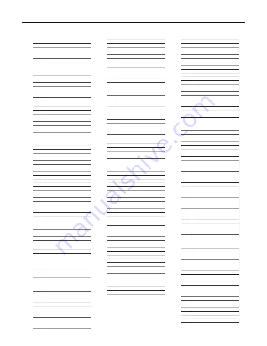
  VF   HR12-14RA-20SC (Hirose)

Pin#

Signal

1

VF+1V

VF+1V

3

UNREG_GND

4

VF-PBOUT_GND

5

VF-PBOUT_GND

6

VF-YOUT

7

VF-YOUT_GND

8

VF_CLK

9

VF_WR

10

VF_DATA

11

UNREG_GND

1

ZEBRA_SW

13

PEAKING

14

TA_BOX_ACT

15

VF-PROUT

16

VF-PBOUT

17

VF_SW3

18

FRONT_VR

19

TA_TALLY

0

F_GND


  REAR VF CN   D02-29S-N-F0 (JAE)

Pin#

Signal

1

VF-YOUT

VF-PBOUT

3

VF-PROUT

4
5

IC_DATA

6

R_TALLY

7

TA_TALLY

8
9

LCD+1V

10

1V

11

VF-YOUT_GND

1

VF-PBOUT_GND

13

VF-PROUT_GND

14

AGND

15

DGND

16
17

UNREG_GND

18
19

F_GND

0

LCD_ACT

1

3

PEAKING_CONT

4

IC_CLK

5

G_TALLY

6

VF_P_REQ

7
8
9


  Buildup unit I/F   QR/P8-20S-C(01) (Hirose)

Pin#

Signal

1

VF_YOUT3

VF_YOUT3_GND

3

VF_PBOUT3

4

VF_PBOUT3_GND

5

VF_PROUT3

6

VF_PROUT3_GND

7

BU_CRN_DATA_H

8

BU_CRN_DATA_C

9

BU_CRN_CONT_H

10

BU_CRN_CONT_C

11

OPT_AC(H)

1

LNS_ID_CO

13

LNS_IP–B

14

IC_DATA

15

IC_CLK

16

LNS_FOCUS_POS

17

LNS_L_TXD

18

BU_ACT

19

DGND

0

OPT_AC(C)

CN# in the
Instructions


  DC IN   HA16RA-4P (Hirose)

Pin#

Signal

1

EXT_GND


3
4

EXT+1V


  MIC1   HA16PRM-3SB(05) (Hirose)

Pin#

Signal

1

MIC1_GND

MIC1(H)

3

MIC1(C)


  MIC2   HA16PRM-3SB(05) (Hirose)

Pin#

Signal

1

MIC_GND

MIC(H)

3

MIC(C)


  TALLY/DC   HR10A-7R-4SC (Hirose)

Pin#

Signal

1

UNREG_GND

R_TALLY_OUT (contact output)

3

G_TALLY_OUT (contact output)

4

1V


  EARPHONE   HSJ0927-0160209 (Hoshiden)

Pin#

Signal

1

PHONE_GND

PHONE_OUT

3


  TRUNK   HR10A-10R-12SC (Hirose)

Pin#

Signal

1

CMD-OUT0(H)

CMD-OUT0(C)

3

CMD-IN0(H)

4

CMD-IN0(C)

5

CMD-OUT1(H)

6

CMD-OUT1(C)

7

CMD-IN(H)

8

CMD-IN1(C)

9

10

DGND

11
1


  LENS   HR10A-10R-12SC (Hirose)

Pin#

Signal

1

LENS_RETSW

LENS_VTRSW

3

AGND

4

ENF_SERVO

5

IRIS_CONT

6

LENS+1V

7

IRIS_POSI

8

H_IRIS_A-R

9

EXTENDER

10

ZOOM_POSI

11

FOCUS_POS/L_RXD

1

S_IRIS_A-R/L_TXD


  FRONT MIC   HA16PRM-3S(05) (Hirose)

Pin#

Signal

1

FRONT_MIC_GND

FRONT_MIC(H)

3

FRONT_MIC(C)

AK-HC3500 connector pin assignment

CN# in the
Instructions


K

  OPT FIBER   EDW.3K.93C.TLC (LEMO)

Pin#

Signal

01

OPT-TX (Mark Band = IN)

0

OPT-RX (Mark Band = OUT)

1

STBYINCOM-T

STBYINCOM-R

3

AC0V(C)

4

AC0V(H)


  INCOM   XLR5-31F77 Female (ITT Cannon)

Pin#

Signal

1

TALK_GND

TALK

3

RECEIVE_GND

4

RECEIVE

5

PGM


  RET CONT   HR10A-7R-6SC (Hirose)

Pin#

Signal

1

INCOM1_MIC_ON

INCOM_MIC_ON

3

AGND

4

RET_CNT3

5

RET_CNT1

6

RET_CNT


  EXT I/O   HR10A-13R-20SC (Hirose)

Pin#

Signal

1

BU_CRN_DATA_H

BU_CRN_DATA_C

3

BU_CRN_CONT_H

4

BU_CRN_CONT_C

5

DGND

6

CRN_INC_R

7

CRN_INC_R_GND

8

CRN_INC_T

9

CRN_INC_T_GND

10

CRN_PGM1_LVL

11

CRN_PGM_LVL

1
13
14

G_TALLY_VF

15

R_TALLY_VF

16

T_TALLY_VF

17

CRANE_ACT

18

EXT+1V

19
0

UNREG_GND




 HD SDI   BNC(75)J-H.FLJ-BPA(40) (Hirose)

Pin#

Signal

1

SDI_OUT

SDI_OUT_GND


  AUX   BNC(75)J-PL72J-BPA (Hirose)

Pin#

Signal

1

AUX

AUX_GND


  PROMPT/GL   BCJ-R/1 (Canare)

Pin#

Signal

1

PROMPT/GL_IN

PROMPT_GND/GL_IN_GND


  REMOTE   HA10A-10R-10SC (Hirose)

Pin#

Signal

1

CAM_DATA(H)

CAM_DATA(C)

3

CAM_CONT(H)

4

CAM_CONT(C)

5
6
7
8
9

RCOP+1V

10

UNREG_GND

Содержание AK-HC3500P

Страница 1: ...Before operating this product please read the instructions carefully and save this manual for future use Operating Instructions Multi Format Camera Model No AK HC3500P ...

Страница 2: ...ses and can radiate radio frequency energy and if not installed and used in accordance with the instruction manual may cause harmful interference to radio communications Operation of this equipment in a residential area is likely to cause harmful interference in which case the user will be required to correct the interference at his own expense Warning To assure continued FCC emission limit compli...

Страница 3: ...n to avoid injury from tip over 13 Unplug this apparatus during lightning storms or when unused for long periods of time 14 Refer all servicing to qualified service personnel Servicing is required when the apparatus has been damaged in any way such as power supply cord or plug is damaged liquid has been spilled or objects have fallen into the apparatus the apparatus has been exposed to rain or moi...

Страница 4: ... new chassis When this Multi Format Camera is connected to a CCU AK HCU931 optional accessory not only can HD signals be input and output but SD signals D1 VBS can be output and RET PROMPT signals can be input as well The iris pedestal gain and other camera adjustments can be carried out by remote control using a unit such as the ROP AK HRP931 or MSU AK MSU935 available as optional accessories Acc...

Страница 5: ...ternal heat buildup can cause a fire DO S Refer any servicing to qualified service personnel Handle the camera with care Protect the precision made lens by placing the lens cap over when the camera is not in use If the lens is not installed protect the surface of the prism by placing the body cap into the lens mount hole Use a mild blower or lens cleaning tissue designed for coated lenses to clean...

Страница 6: ... Controls and their functions ...

Страница 7: ... Controls and their functions ...

Страница 8: ...onnected and it goes off if the CCU is not connected Power circuit breaker BREAKER This shuts off the power in the event of an overcurrent while the DC 12 V power supply is used To reset it press the circuit breaker button INCOM connectors 1 2 INCOM1 INCOM2 The INCOM or headset plugs are connected here INCOM1 MIC ON OFF switch MIC1 TALK This is the INCOM1 MIC ON OFF selector switch INCOM1 level co...

Страница 9: ...tput signals of the PROMPT output connector ROP connector REMOTE The remote operation panel ROP optional accessory is connected to this connector External power supply input connector DC IN The input of the external DC power supply is connected to this connector DC 10 8 V to 17 V MIC1 selector switch LINE FRONT MIC MIC This is used to switch the input signal to LINE FRONT MIC or rear MIC Rear MIC1...

Страница 10: ...ed moves the cursor to the setting items The menu settings are established by operating this dial button For details on the menu operations refer to the section on the menu operations Electronic shutter selector switch SHUTTER This is set to ON when the electronic shutter is to be used When it is set to the SEL position the shutter speed is switched in the preset range and the mode is also switche...

Страница 11: ...ace Lens clamp lever 4 Insert the cable into the cable clamp and connect it to the lens connector Lens connector For details on handling the lens refer to the instructions that accompany the lens Depending on the lens mounted it may be necessary to perform the following lens and camera adjustments 1 Flange back adjustment for the lens 2 Auto iris operation speed adjustment for the lens 3 White sha...

Страница 12: ...is to manual and open the iris 3 Set the lighting in such a way that the appropriate video output level is obtained at a distance of about 9 9 ft 3 m from the flange back adjustment chart If the video level is too high use a filter or shutter 4 Loosen the screw that secures the F f flange focus ring Depending on the lens concerned this ring may be marked as the F b flange back ring Note 5 Set the ...

Страница 13: ...knob 3 Tighten the stopper screw securely Stopper screw 4 Connect the plug to the VF connector When connecting the plug to the VF connector ensure that it is fully and securely inserted Note Detaching the viewfinder 1 Check that the camera s POWER switch is at the OFF position 2 Loosen the stopper screw pull up the knob on the mounting plate and slide the viewfinder along and off the plate Stopper...

Страница 14: ...rew Stopper screw Forward or backward position adjustment 1 Rotate the viewfinder forward backward position fixing lever towards the outside to release it from the locked position Viewfinder forward backward position fixing lever Viewfinder 2 Move the viewfinder forward or backward to adjust its position 3 Rotate the viewfinder forward backward position fixing lever in the opposite direction until...

Страница 15: ...can be mounted on the viewfinder 1 Open the microphone holder Microphone holder 2 Mount the microphone and tighten up the clamp screw Clamp screw 3 Connect the microphone cable to the front MIC1 connector on the camera Front MIC1 connector 4 If the audio channel whose signals are to be recorded so requires set the MIC1 selector switch to FRONT MIC MIC1 selector switch ...

Страница 16: ...d Now check that the camera is secured properly Detaching the camera from the tripod attachment While pushing the red lever move the black lever in the direction of the arrow and slide the camera toward the back Red lever Tripod attachment Black lever Note If the pin of the tripod attachment fails to return to its original position after the camera has been detached push the red lever again and si...

Страница 17: ...controlled The basic system configuration includes the lens Multi Format Camera viewfinder camera control unit CCU and remote operation panel ROP System block diagram Microphone Kit AJ MC700 2 Electronic HD Viewfinder AJ HVF21 Handy lens Multi Format Camera AK HC3500 Tripod Attachment SHAN TM700 SD memory card Master Setup Unit AK MSU935 8 LCD Viewfinder AK HVF931A Remote Operation Panel AK HRP931...

Страница 18: ...r with the ROP 4 2 Electronic HD Viewfinder 2 VF AJ HVF21 This is the viewfinder for the Multi Format Camera 5 8 LCD Viewfinder LCD VF AK HVF931A This is the LCD viewfinder for the Multi Format Camera It can be used at the same time as the 2 viewfinder It can still be operated when the system is built up 6 Buildup Unit AK HBU3500 This is an adapter used to mount a large lens on the Multi Format Ca...

Страница 19: ...efore proceeding with the connections set the CCU power switch to the OFF position Connect the optical cable to the Multi Format Camera and CCU Connect the ROP cable to the CCU and ROP When the camera power switch is set to ON after the CCU main power switch has been set to ON the camera can be controlled using the ROP Upon completion of shooting set the CCU camera power switch and main power swit...

Страница 20: ...connections 2 with Buildup Unit Large lens Buildup Unit AK HBU3500 8 LCD Viewfinder AK HVF931A Multi Format Camera AK HC3500 Remote Operation Panel AK HRP931 Camera Control Unit AK HCU931 ROP cable Optical cable ...

Страница 21: ...Format Camera AK HC3500 Multi Format Camera AK HC3500 Camera Control Unit 11 AK HCU931 Camera Control Unit 12 AK HCU931 Remote Operation Panel 11 AK HRP931 Remote Operation Panel 12 AK HRP931 Buildup Unit AK HBU3500 Optical cable Optical cable A multiple number of cameras up to 12 units can be controlled in one location using the MSU The cameras can be controlled by both the ROPs and MSU ...

Страница 22: ...splay This indicates the automatic adjustment memory selected for the white balance A The WHITE BAL switch is set to A B The WHITE BAL switch is set to B P The WHITE BAL switch is set to PRST Gain display This indicates the video amplifier s gain setting in dB which has been selected by the gain selector switch Audio CH1 and CH2 displays The audio levels are displayed here separately for audio CH1...

Страница 23: ... that item s menu Entering the menu data After accessing the item menus enter the respective data 1 Turn the JOG dial to select the menu item to be set 2 When the JOG dial is pressed the setting of the item indicated by the arrow flashes 3 Turn the JOG dial to change the setting 4 When the JOG dial is pressed the data is entered Note Bear in mind that if in step 3 the MENU switch is set to OFF whi...

Страница 24: ...he setting flashes one character at a time press the JOG dial to move the flashing toward the right 1 When the JOG dial is pressed flashing moves toward the right 2 Turn the JOG dial to change the setting 3 When the JOG dial is now pressed the data is entered ...

Страница 25: ...25 Setting menu configuration Hierarchical menus USER MENU ...

Страница 26: ...26 Setting menu configuration Hierarchical menus USER MENU ...

Страница 27: ...27 Setting menu configuration Hierarchical menus USER MENU ...

Страница 28: ...28 Setting menu configuration Hierarchical menus USER MENU ...

Страница 29: ...29 Setting menu configuration Hierarchical menus USER MENU ...

Страница 30: ... 6M 15 0M 15 5M 16 1M 16 7M 17 3M 18 0M 18 6M 18 8M 19 0M 19 2M 19 5M 19 9M 20 3M 20 9M 21 5M 22 4M 23 6M 25 4M 28 6M 37 1M 12 4M HD Offset Gain 0 to 5 0 HD Crisp 0 to 63 30 D1 Peak FREQ 2 0M 2 3M 2 7M 3 4M 4 5M 6 8M 13M 6 8M D1 Offset Gain 0 to 5 0 D1 Crisp 0 to 63 30 VBS Peak FREQ 2 0M 2 3M 2 7M 3 4M 4 5M 6 8M 13M 6 8M VBS Offset Gain 0 to 5 0 VBS Crisp 0 to 63 30 Cursor Cursor OFF ON OFF Cursor...

Страница 31: ...MARK OFF LENS EXT PTT Back Light 1 to 70 20 RET Mode NORM TOGGLE SEQ NORM Lens I F Serial Analog Analog B U Lens BOX PORTABLE BOX LED Gamma Off OFF ON OFF Shutter OFF ON OFF Extender OFF ON OFF MONI OUT OFF ON OFF FAN Off OFF ON OFF Master Gain OFF ON OFF Black Gamma OFF ON OFF 7 VF VF FAN Speed NORM LOW NORM Peak Slice OFF LOW MID HI OFF Peak FREQ 8 MHz 15 MHz 8 MHz INCOM Set 1 INC1 MIC Type DYN ...

Страница 32: ...lare R 100 to 100 0 Flare B 100 to 100 0 Gain G 800 to 800 0 Gain R 800 to 800 0 Gain B 800 to 800 0 White SHD Correct OFF ON ON H SAW R G B 100 to 100 0 H PARA R G B 100 to 100 0 V SAW R G B 100 to 100 0 V PARA R G B 100 to 100 0 Gamma Gamma ON OFF ON Gamma M 0 600 to 0 300 0 450 Gamma R 75 to 75 0 Gamma B 75 to 75 0 Black Gamma OFF ON OFF Black Gamma M 32 to 32 0 Black Gamma R 20 to 20 0 Black G...

Страница 33: ...27 0 B_Mg Phase 128 to 127 0 Color Correct2 Matrix OFF ON OFF Linear OFF A B OFF 12axes OFF A B OFF Mg Satu 128 to 127 0 Mg Phase 128 to 127 0 Mg_R Satu 128 to 127 0 Mg_R Phase 128 to 127 0 R Satu 128 to 127 0 R Phase 128 to 127 0 R_Ye Satu 128 to 127 0 R_Ye Phase 128 to 127 0 Ye Satu 128 to 127 0 Ye Phase 128 to 127 0 Ye_G Satu 128 to 127 0 Ye_G Phase 128 to 127 0 Detail1 V DTL 0 to 63 22 H DTL 0...

Страница 34: ...TE CANCEL execution items Cursor OFF ON OFF H Cursor 1 to 1920 960 V Cursor 1 to 540 270 ZEBRA OFF A B A B OFF Effect MEM A B A B A B Skin Tone Detail2 Skin Tone DTL ON OFF OFF MEM Select A B A Skin Tone Crisp 63 to 0 to 63 0 Phase 0 to 359 0 Width 0 to 255 0 Saturation 0 to 255 0 Table of adjustment setting ranges ...

Страница 35: ...EXECUTE Yes No Lens Edit Gain R 800 to 800 0 Gain G 800 to 800 0 Gain B 800 to 800 0 Flare R 100 to 100 0 Flare G 100 to 100 0 Flare B 100 to 100 0 W H SAW R G B 100 to 100 0 W H PARA R G B 100 to 100 0 W V SAW R G B 100 to 100 0 W V PARA R G B 100 to 100 0 Store execution items Cancel execution items Option 2 Iris Cont Auto Iris ON OFF OFF Window Select 1 to 8 3 1 Iris Level 0 to 100 60 Peak Rati...

Страница 36: ...8 1 SC H Fine 255 to 255 0 Shutter Shutter OFF ON OFF SYNCHRO OFF ON OFF Mode Fixed at SHUTTER SHUTTER Speed When SHUTTER is ON SYNCHRO is OFF 100 125 250 500 1000 2000 When SHUTTER is ON SYNCHRO is ON 60 9 Hz to 99 8 Hz When SHUTTER is OFF SYNCHRO is ON 60 9 Hz to 99 8 Hz When SHUTTER is OFF SYNCHRO is OFF 100 125 250 500 1000 2000 When SHUTTER is ON SYNCHRO is OFF 100 When SHUTTER is ON SYNCHRO ...

Страница 37: ...lect the number of the file to be loaded or stored here Setting range 1 to 8 The files on the SD card have filenames which range from 3500cm01 dat for File No 1 to 3500cm08 dat for File No 8 The SD card may not work properly if files have been edited using a personal computer or other device EXECUTE The item set in Mode is executed here When the arrow cursor is moved to EXECUTE and the JOG dial bu...

Страница 38: ...al 1 PHONE_GND 2 PHONE_OUT 3 TRUNK HR10A 10R 12SC Hirose Pin Signal 1 CMD OUT0 H 2 CMD OUT0 C 3 CMD IN0 H 4 CMD IN0 C 5 CMD OUT1 H 6 CMD OUT1 C 7 CMD IN H 8 CMD IN1 C 9 10 DGND 11 12 LENS HR10A 10R 12SC Hirose Pin Signal 1 LENS_RETSW 2 LENS_VTRSW 3 AGND 4 ENF_SERVO 5 IRIS_CONT 6 LENS 12V 7 IRIS_POSI 8 H_IRIS_A R 9 EXTENDER 10 ZOOM_POSI 11 FOCUS_POS L_RXD 12 S_IRIS_A R L_TXD FRONT MIC HA16PRM 3S 05...

Страница 39: ...39 External dimension drawings Unit inch mm 14 3 16 360 10 1 4 260 4 1 8 105 5 5 16 135 ...

Страница 40: ...ected by camera menu 2 INCOM 0 dBm 600 ohms XLR 5 pin female 2 Mixing is controlled separately for PGM1 and PGM2 3 HD SDI1 HD SDI2 output HD signal 0 8 Vp p 75 ohms BNC The HD SDI2 signal output can be added to the regular images using the camera menu item setting and switched to the VF or RET image output 4 Prompt output VBS signal 1 Vp p 75 ohms BNC G L input Tri level SYNC or black burst BNC Se...

Страница 41: ...41 Memo ...

Страница 42: ...42 Memo ...

Страница 43: ...43 ...

Страница 44: ... Marketing Department 52 West Gude Drive Rockville MD 20850 301 738 3840 Broadcast PARTS INFORMATION ORDERING 9 00 a m 5 00 p m PST 800 334 4881 24 Hr Fax 800 334 4880 Emergency after hour parts orders 800 334 4881 TECHNICAL SUPPORT Emergency 24 Hour Service 800 222 0741 Panasonic Canada Inc 5770 Ambler Drive Mississauga Ontario L4W 2T3 905 624 5010 Panasonic de Mexico S A de C V Av angel Urraza N...

Отзывы: