background image

AJ8 (J8)

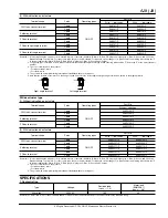
2. Characteristics

Remark: Test conditions are in accordance with EN61058-1, UL1054 and JIS C 6571.

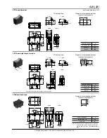
DIMENSIONS

mm General tolerance: 

±

0.5

Expected life
(Min. operations)

Mechanical

Min. 5 

×

 10

4

 (at 20 cpm.)

Electrical

Min. 10

4

 (at 7 cpm., at rated load)

Initial insulation resistance (Between terminals)

Min. 100 M

 (at 500V DC measured by insulation resistive meter)

Initial breakdown voltage (Between terminals)

2,000 Vrms detection current: 10 mA

Initial contact resistance (By voltage drop at 1A, 2 to 4V DC)

Max. 100m

Temperature rise

at 6 

×

 10

3

 ope. or less

Max. 30

°

C (UL1054)

from 6 

×

 10

3

 ope. to 10

4

Max. 55

°

C (EN61058-1)

Vibration resistance

10 to 55 Hz at double amplitude of 1.5mm

Shock resistance

Min. 490m/s

2

{50 G}

Actuator strength

40 N {4.08kgf} for 1 minute (operating direction)

Terminal strength (.250 Quick-connect terminal)

100 N {10.2kgf} for 1 minute or more (Pull & push direction)

Ambient temperature

–25

°

C to +85

°

C (Not freezing below 0

°

C)

Flame retardancy

UL94V-0

Tracking resistance

Min. 175

Operating force
(reference characteristics)

1-pole

2.45 

±

 1.47N {0.25 

±

0.15kgf}

2-pole

4.5 

±

 2.5N {0.46 

±

0.25kgf}

Contact material

AgSnO

2

 alloy

1. .250 Quick-connect terminal/Short guard type

ON

OFF

30

15

2-pole

1-pole

12.8

10

19.5

16

7.7

10.6

12.5

4.375

8.75

0.8

28

15

6.35

2

4.4

32

°

±

4

1.75 dia.

Long guard type

.250 Quick-connect terminal

ON

OFF

30

16

7.7

10.6 11

28

15

6.35

2

4.4

32

°

±

4

1.75 dia.

Diagram of recommended 

locations for panel 

mounting holes

Panel thickness

X

0.75 to 1.25

28.2

1.25 to 2

28.4

2 to 3

28.8

12.9

+

0.1

0

X

+

0

0.1

+

0

0.1

+

0

0.1

2. Soldering terminal

ON

OFF

30

15

2-pole

1-pole

12.8

10

19.5

16

7.7

10.6

12.5

4.375

8.75

0.8

28

15

2.5

2

3.5

32

°

±

4

Long guard type

Soldering terminal

OFF

ON

30

16

7.7

10.6 11

28

15

2.5

2

3.5

32

°

±

4

Diagram of recommended 

locations for panel 

mounting holes

Panel thickness

X

0.75 to 1.25

28.2

1.25 to 2

28.4

2 to 3

28.8

12.9

+

0.1

0

X

+

0

0.1

+

0

0.1

+

0

0.1

All Rights Reserved © C

OPYRIGHT

 Matsushita Electric Works, Ltd.

Содержание AJ8

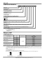
Страница 1: ...FREE CONTACT TYPE Models with cadmium free contacts have been introduced in order to reduce environmentally harmful substances F is affixed to the end of the part number We ask customers who are currently using products with cadmium containing contacts no F at the end of the part number to please make the switch to models with cadmium free contacts When switching operating life may differ dependin...

Страница 2: ...F Soldering terminal 1 pole AJ8110 F 2 pole AJ8210 F PC board terminal 1 pole AJ8120 F 2 pole AJ8220 F PC board right angle terminal 1 pole AJ8130 F 2 pole AJ8230 F PC board left angle terminal 1 pole AJ8140 F 2 pole AJ8240 F Actuator indication 0 No indication 1 indication 2 indication 8 AJ8 switch Nil Standard actuator W Wide actuator Actuator color W White B Black R Red Z Dark gray H Light gray...

Страница 3: ...e G Green and Y Yellow 2 The color of indication on the actuator For white actuator black For others white 3 They come with a stamp indicating international standards without your request SPECIFICATIONS 1 Contact rating Remark The motor load is in accordance with EN61058 1 Inrush current can be switched up to the value of 6 times the indicated rating Terminal shape Poles Operating types Part No Wi...

Страница 4: ...ion Ambient temperature 25 C to 85 C Not freezing below 0 C Flame retardancy UL94V 0 Tracking resistance Min 175 Operating force reference characteristics 1 pole 2 45 1 47N 0 25 0 15kgf 2 pole 4 5 2 5N 0 46 0 25kgf Contact material AgSnO2 alloy 1 250 Quick connect terminal Short guard type ON OFF 30 15 2 pole 1 pole 12 8 10 19 5 16 7 7 10 6 12 5 4 375 8 75 0 8 28 15 6 35 2 4 4 32 4 1 75 dia Long g...

Страница 5: ...4 PC board pattern 15 0 1 8 0 1 3 0 2 15 0 1 3 0 2 1 2 0 1 1 2 0 1 4 375 0 1 2 pole 1 pole Diagram of recommended locations for panel mounting holes Terminal side 12 9 0 1 0 X 21 0 0 3 17 5 0 3 Panel thickness X 0 75 to 1 25 28 2 1 25 to 2 28 4 2 to 3 28 8 0 0 1 0 0 1 0 0 1 5 Wide actuator type OFF ON 32 32 4 25 2 pole 1 pole 21 8 19 19 5 16 7 7 10 6 21 4 375 8 75 29 4 15 6 35 4 4 1 75 dia 0 8 2 D...

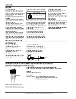
Страница 6: ...the switch unit use a neutral detergent diluted with water Do not use acidic or alkaline solvents as they may damage the switch Furthermore be careful not to get any of the detergent solution inside of the switch while cleaning it 4 Environment Avoid using and storing these switches in a location where they will be exposed to corrosive gases silicon or high dust levels all of which can have an adv...

Отзывы: