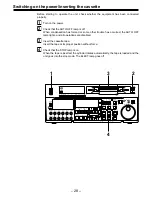
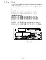
background image

– 32 –

Jog/shuttle

Jog mode

1

Push the search dial to the “in” position.
Be sure that the JOG lamp lights.

2

Rotate the search dial.
The dial’s clickstops are cleared, and the tape is played back at the speed (–1

×

 to +1

×

normal  speed)  corresponding  to  the  speed  at  which  the  dial  is  turned.  When  the  dial
rotation is stopped, a still picture appears. The playback picture is noise-free.

3

To transfer from the jog mode to another mode, press the appropriate button.

Shuttle mode

1

Push the search dial to release it from the “in” position. The SHTL lamp lights, and the
unit goes into the shuttle mode.

Immediately after the power has been turned on, rotate the search dial and set it to the
centre position.

2

Set the SHTL/SLOW switch to SHTL or SLOW.

3

Rotate the search dial.
When  the  SHTL/SLOW  switch  has  been  set  to  SHTL,  the  playback  picture  speed  is
varied from 0 to ±32

×

 normal speed depending on the position of the dial. The playback

picture  speed  can  be  switched  to  ±8.4

×,

  ±16

×

  and  ±32

×

  normal  speed  with  setting

menu No. 101 (SHTL MAX).
The  dial’s  centre  position  is  a  clickstop  where  a  still  picture  appears  as  the  playback
image.  When  the  SHTL/SLOW  switch  has  been  set  to  SLOW,  the  playback  picture
speed is varied from –4.1 to +4.1

×

 normal speed depending on the position of the dial.

The maximum speed can be selected using the setup menu No. 308 (VAR FWD MAX)
and No. 309 (VAR REV MAX). However, noise appears at speeds other than –1 to +1

×

normal speed.
The  dial’s  centre  position  is  a  clickstop  where  a  still  picture  appears  as  the  playback
image. The playback picture is noise-free.

4

To  transfer  from  the  shuttle  mode  to  another  mode,  press  the  STOP  button  or  other
button.

<Note>

When the unit leaves the factory, its operation is set up so that it will be transferred to the
shuttle or jog mode when the search dial is rotated. If it is inconvenient for operation to be
transferred  to  the  variable-speed  mode  directly,  it  can  also  be  transferred  through  the
search button.
Set setup menu No. 100 (SEARCH ENA) to KEY.

Содержание AJ-HD150FE

Страница 1: ...Operating Instructions Digital HD Video Cassette Recorder AJ FE ...

Страница 2: ...HERE IS A DAN GER OF SEVERE ELECTRICAL SHOCK IF THE CUT OFF PLUG IS INSERTED INTO ANY 13 AMP SOCKET If a new plug is to be fitted please observe the wiring code as shown below If in any doubt please consult a qualified electrician WARNING THIS APPLIANCE MUST BE EARTHED IMPORTANT The wires in this mains lead are coloured in accordance with the following code Green and Yellow Earth Blue Neutral Brow...

Страница 3: ...ds away from the unit before operation WARNING TO REDUCE THE RISK OF FIRE OR SHOCK HAZARD KEEP THIS EQUIPMENT AWAY FROM ALL LIQUIDS USE AND STORE ONLY IN LOCA TIONS WHICH ARE NOT EXPOSED TO THE RISK OF DRIPPING OR SPLASHING LIQUIDS AND DO NOT PLACE ANY LIQUID CONTAIN ERS ON TOP OF THE EQUIPMENT Do not insert fingers or any objects into the video cassette holder Avoid operating or leaving the unit ...

Страница 4: ...Features 5 Controls and their functions 7 Front panel 7 Connector area 16 Operations using the front panel bottom controls 19 Operations using the front panel top controls 22 Connections 26 Tapes 27 Switching on the power inserting the cassette 28 STOP STAND BY mode 29 Recording 30 Playback 31 Jog shuttle 32 Manual editing 33 Preroll 34 Automatic editing deck to deck 35 Switch settings and adjustm...

Страница 5: ... is a 4U digital VTR Using the rack mounting adapters optional accessory AJ MA75P it can also be easily housed in a 19 inch rack Up to 46 minutes of recording The L size cassettes max 46 minutes are used for recording The tape is 1 4 inch in width which makes for a compact design High picture quality The unit s high picture quality is achieved by 4 2 2 HD component signal recording using a recordi...

Страница 6: ...feature They output composite signals during DVCPRO reciprocal playback DV playback or down conversion At all other times they output the black burst signal AES EBU audio input output connectors Digital audio input output connectors for 8 channels are featured as a standard accessory 9 pin RS 422A and RS 232C remote control connectors In addition to the standard 9 pin serial remote RS 422A control...

Страница 7: ...VO REC FF REC INHIBIT PLAYER EXT EE MODE REMOTE PUSH REV FWD RECORDER LOCAL CONTROL CH 1 1 ASMBL PREVIEW REVIEW AUTO EDIT PREROLL TRIM A IN IN SET OUT A OUT MULTICUE INSERT VIDEO CH1 5 CH2 8 CH3 7 CH4 8 CUE TC CH 4 OFF POWER CH CONDITION ENTER ESCAPE SHIFT METER FULL FINE MONITOR SELECT LEVEL HEADPHONES CH 1 5 CH 2 6 CH 3 7 CH 4 8 CUE REC L R PB PULL FOR VARIABLE PULL OPEN PULL OPEN CH 5 CH 8 2 3 ...

Страница 8: ...s lights when the error rates for the video and audio playback signals are both acceptable Amber This lights when the error rate for the video or audio playback signals has deteriorated The playback picture will remain normal even when this lamp lights Red This lights when the video or audio signals are subject to rectification or interpolation 5 5 5 5 5 Scroll buttons These are used for left and ...

Страница 9: ...A A A EDIT button For manual editing press both this button and the PLAY button together during playback When the button is pressed in the stop mode the input mode signals selected by the ASMBL or INSERT button can be monitored in the EE mode The original picture and sound are restored when the STOP button is pressed When the button is pressed during playback search 1 fast forward or rewind the in...

Страница 10: ... control The unit s editing and tape transport buttons now control the player s functions RECORDER button When this button is pressed its lamp lights and the editing and tape transport buttons control the recorder s the unit s functions Both lamps light and the recorder functions as the master unit for Parallel Run operations if the PLAYER or RECORDER button is pressed while ENA has been selected ...

Страница 11: ... the tape travels in the REV direction provided that the lamp in the search button has lit STILL This lights in the JOG mode while the dial is kept stationary and the tape stops travelling provided that the lamp in the search button has lit It lights in the SHTL mode provided that the dial is at the STILL position FWD This lights when the dial is turned clockwise and the tape travels in the FWD di...

Страница 12: ...screen connected to the recorder T T T T T IN A IN SET OUT A OUT buttons When IN A IN or OUT A OUT button is pressed together with the SET button the IN A IN or OUT A OUT point is entered A IN and A OUT are used during audio split editing to enter an audio IN or OUT point that differs from the video In or OUT point While an IN A IN or OUT A OUT point is selected the IN A IN or OUT A OUT button cor...

Страница 13: ...data which has been changed by the SHIFT and ADJ buttons Also Pressing this button when the TC or UB value are not set enables the TCG or UBG setting values to be confirmed RESET When this button is pressed in the CTL mode the display is reset to 00 00 00 00 In the CTL mode the entered edit points are cleared In the TC UB mode the generator is reset when the button is pressed together with the SHI...

Страница 14: ... disabled when the channel except OFF has been selected for setup menu No 735 MONITOR MIX R The L or R lamp on the level metre display lights to indicate which signal is now being selected When the unit is set to AUTO in No 745 MONI CH SEL on the setup menu then the display will change according to the monitor output The lamp flashes if the channels selected by AUDIO CH SELECT do not appear on the...

Страница 15: ... There are two types of VTR information HOURS METER information and WARNING information Switching between these types is enabled by pressing the search button Indicated on the HOURS METER screen are the power on time drum rotation time tape travel time loading count and power ON OFF time etc Indicated on the WARNING screen are the warning g MODE SEL button This is used to initiate a MULTI CUE oper...

Страница 16: ... M O T E OUT 2 OUT 3 AUDIO OUT PUSH PUSH PUSH PUSH 4 1 2 3 5 6 7 89 A B C D E F G 4 1 Power mains socket This is for connecting the unit to the power mains socket using the power cord provided 2 SIGNAL GND terminal This terminal is connected to the signal ground terminal of the connected unit in order to reduce noise It is not connected to ground for safety purposes 3 Fuse holder This contains a f...

Страница 17: ...nectors for the HD digital component audio and video signals that comply with the SMPTE 292M standard The TC menu or other information is output from the HD SDI OUT3 connector with the information superimposed onto the signals SD SERIAL DIGITAL COMPONENT AUDIO VIDEO OUT connectors These are the output connectors for the digital component audio and video signals that comply with the SMPTE 259M C 27...

Страница 18: ...nu setting B B B B B SD REF OUT connector This is the output connector for the NTSC external synchronization signal black burst signal C C C C C DIGITAL AUDIO IN OUT connector This I O connector is for digital audio signals which comply with the AES EBU standard D Remote control connectors The unit can be controlled from an external source by connecting the unit with another unit or an external co...

Страница 19: ...be registered in these buttons However the submenus of setup menu item No 680 BLANK LINE cannot be registered Registration method The items are registered as they are selected by the menu driven system Connect the TV monitor to the VIDEO OUT3 connector in the unit s connector area and display the registration menu Press the SETUP button The message indicating that the registration steps can now be...

Страница 20: ...t The number of the button corresponding to the button that was pressed is now displayed When the same button is pressed again the button number display is released To register more items repeat steps 3 and 4 Press the SAVE EXIT button The registered information is now saved in the memory When more than one item has been registered the information will be stored in sequence starting with the lowes...

Страница 21: ...as pressed is returned to the non registration status CANCEL button This is for cancelling the reset operation Example of the operation menu displayed for resetting VTR statuses which have been registered PLAY button Whatever statuses have been registered in the STATUS 1 to 3 buttons c are reset to the factory settings STATUS 1 to 3 buttons The button which was pressed is returned to the non regis...

Страница 22: ...s 4 or more press the SCROLL buttons 5 to scroll the display to the left or right When the number of registered items is less than 3 appears in the sections where items have not been registered 2 1 Registered menu item displays The registered setup menu items are displayed by pressing the PROG MENU 1 to 4 buttons c Example of registered menu item display Digit 1 Cursor for selecting items mark ind...

Страница 23: ...ng the mark indicating that a setting is being changed appears at digit 1 to indicate the status If the item allows for a wide range of variation in its setting continue to press one of the SCROLL buttons 5 while holding down the SHIFT button 8 and the setting can be incremented or decremented at a higher speed Entering the setting Press the ENTER button 6 to enter the setting change and return to...

Страница 24: ...scertained from the tape s playback signals 59 94 The tape has been recorded at a field fre quency of 59 94 Hz 60 The tape has been recorded with at a field fre quency of 60 Hz This indicates the field frequency at which the recording is to be made on the tape 59 94 The recording will be made on the tape at a field frequency of 59 94 Hz 60 The recording will be made on the tape at a field frequenc...

Страница 25: ...SER3 is selected USER4 USER4 is selected USER5 USER5 is selected This indicates the tape speed in JOG SLOW SHTL mode JOG mode REV reverse STILL stop FWD forward is indicated SLOW mode Current speed is indicated SHTL mode Current speed is indicated Other than above Indication is blank SETUP NUMBER TAPE SPEED 007 008 Item as it ap pears on VTR status display SETUP SPEED Name of registration menu ite...

Страница 26: ...H PUSH L G D CH1 2 AUDIO IN CH3 4 CH5 6 CH7 8 OUT 1 OUT 1 SUPER SUPER IN OUT 2 OUT 3 SD SDI ANALOG DIGITAL AUDIO SD SDI OPTION OPTION HD SDI R E M O T E OUT 2 OUT 3 AUDIO OUT PUSH PUSH PUSH PUSH Audio monitor output connectors Digital audio input connectors Digital audio output connectors Analog audio input connectors SD SDI output connector HD SDI input audio video connector Analog audio output c...

Страница 27: ... cassette adapter will cause malfunctioning Tapes with a maximum playback time of maximum of 33 minutes AJ 5P23MP AJ 5P33MP Tapes with a maximum recording playback time of maximum of 46 minutes AJ HP32LP AJ HP46LP Standard playback cassette tapes for consumer use DV DVCAM For playback set the setup menu No 022 PB FORMAT to AUTO or setup menu No 023 FORMAT SEL to DV or DVCAM Use of Panasonic s cons...

Страница 28: ...lly the tape is loaded and the unit goes into the stop mode The EJECT lamp goes off ON AUDIO CH SELECT SHIFT ADJ TC SET START TC CTL RESET TC INT TC TAPE UB STAND BY EDIT PLAY REW STOP SERVO REC FF REC INHIBIT PLAYER EXT EE MODE REMOTE PUSH REV FWD RECORDER LOCAL CONTROL CH 1 1 ASMBL PREVIEW REVIEW AUTO EDIT PREROLL TRIM A IN IN SET OUT A OUT MULTICUE INSERT VIDEO CH1 5 CH2 8 CH3 7 CH4 8 CUE TC CH...

Страница 29: ... When the button is pressed during the standby OFF mode the unit goes to the standby ON mode Still Timer Setting Page 81 indicates the settings for menu item 400 Still Timer set Still Timer settings 4 and below will best protect the tape ON AUDIO CH SELECT SHIFT ADJ TC SET START TC CTL RESET TC INT TC TAPE UB STAND BY EDIT PLAY REW STOP SERVO REC FF REC INHIBIT PLAYER EXT EE MODE REMOTE PUSH REV F...

Страница 30: ...e audio CH1 CH2 CH3 CH4 CH5 CH6 CH7 CH8 and analogue cue channels selected by the setup menu item No 700 setting Normally keep the audio input output level controls pushed in unity value The audio signals will be recorded at the proper level 2 To adjust the recording level pull out the controls and adjust them With the CUE signal adjust the control in such a way that 20 dB will not be exceeded Not...

Страница 31: ...level Pull out the audio level controls and turn them clockwise or counterclockwise to adjust the levels Normally they are kept in the pushed in state unity value 4 To end playback press the STOP button The VTR now goes into the stop mode Note Check that the SERVO lamp is lit during playback If it flashes or if it is off the images played back will be disturbed ...

Страница 32: ...tion of the dial The playback picture speed can be switched to 8 4 16 and 32 normal speed with setting menu No 101 SHTL MAX The dial s centre position is a clickstop where a still picture appears as the playback image When the SHTL SLOW switch has been set to SLOW the playback picture speed is varied from 4 1 to 4 1 normal speed depending on the position of the dial The maximum speed can be select...

Страница 33: ...nals to be edited and check that its lamp is on 3 Press the PLAY button 4 Search for the position where the editing is to be commenced IN point while viewing the TV monitor and press the PLAY and EDIT buttons together at the IN point 5 Press the STOP or PLAY button at the position where editing is to be completed OUT point while viewing the TV monitor The unit goes into the stop mode and editing i...

Страница 34: ...nt has not been entered the tape is rewound for the duration set by setup menu 000 from the position where the button was pressed and the unit then goes into the stop mode Notes The time code or CTL signal must be continuously recorded between the edit IN point and preroll point When the IN point has not been entered whether to enter the IN point and perform preroll or to perform preroll without e...

Страница 35: ...rts The basic steps taken for editing are as follows 1 Set the CONTROL switch to REMOTE on the player and to LOCAL on the recorder 2 Select the editing mode 3 Enter the edit points of the recorder and player 4 Check and modify the edit points 5 Check Preview before proceeding with the editing 6 Proceed with the editing 7 Check Review the recording that has resulted from the editing ...

Страница 36: ...CH 4 8 CUE REC L R PB PULL FOR VARIABLE PULL OPEN PULL OPEN CH 5 CH 8 2 3 4 5 6 7 8 JOG SHTL SLOW EJECT M cassette ADAPTER Caution Do not insert S cassette without adapter Set the time counter display to TC or CTL Set the POWER switch to ON Set the CONTROL switch to REMOTE Adjust the playback level ON AUDIO CH SELECT SHIFT ADJ TC SET START TC CTL RESET TC INT TC TAPE UB STAND BY EDIT PLAY REW STOP...

Страница 37: ...VTR PLAYER Press this button to operate the player VTR and enter the edit points RECORDER Press this button to operate the recorder VTR this unit and enter the edit points ON AUDIO CH SELECT SHIFT ADJ TC SET START TC CTL RESET TC INT TC TAPE UB STAND BY EDIT PLAY REW STOP SERVO REC FF REC INHIBIT PLAYER EXT EE MODE REMOTE PUSH REV FWD RECORDER LOCAL CONTROL CH 1 1 ASMBL PREVIEW REVIEW AUTO EDIT PR...

Страница 38: ...g a total of four edit points namely the player s IN and OUT points and the recorder s IN and OUT points need to be entered However since the last edit point is calculated automatically only three of these edit points must be entered Negative duration function This function is used by combining setup menu No 300 IN OUT DEL and No 301 NEGA FLASH ON AUDIO CH SELECT SHIFT ADJ TC SET START TC CTL RESE...

Страница 39: ...he duration between the two edit points When only one edit point has been set the duration between the set data and the current tape address When neither edit point has been set the duration of the previously edited interval ON AUDIO CH SELECT SHIFT ADJ TC SET START TC CTL RESET TC INT TC TAPE UB STAND BY EDIT PLAY REW STOP SERVO REC FF REC INHIBIT PLAYER EXT EE MODE REMOTE PUSH REV FWD RECORDER L...

Страница 40: ... RESET button while holding down the IN or OUT button Notes Edit points can be reset only in the CTL mode An edit OUT point can be reset even while editing is in progress The IN and OUT points are automatically reset during the eject mode ON AUDIO CH SELECT SHIFT ADJ TC SET START TC CTL RESET TC INT TC TAPE UB STAND BY EDIT PLAY REW STOP SERVO REC FF REC INHIBIT PLAYER EXT EE MODE REMOTE PUSH REV ...

Страница 41: ...t automatically goes into the stop mode ON AUDIO CH SELECT SHIFT ADJ TC SET START TC CTL RESET TC INT TC TAPE UB STAND BY EDIT PLAY REW STOP SERVO REC FF REC INHIBIT PLAYER EXT EE MODE REMOTE PUSH REV FWD RECORDER LOCAL CONTROL CH 1 1 ASMBL PREVIEW REVIEW AUTO EDIT PREROLL TRIM A IN IN SET OUT A OUT MULTICUE INSERT VIDEO CH1 5 CH2 8 CH3 7 CH4 8 CUE TC CH 4 OFF POWER CH CONDITION ENTER ESCAPE SHIFT...

Страница 42: ...when the next edit point has not yet been entered upon completion of editing the previous edit OUT point will be entered as the IN point and editing is performed accordingly To release the auto tag mode press one of the tape transport buttons PLAY etc Note The entered points are automatically cleared after editing is executed However the previous editing points can be recalled by pressing the TRIM...

Страница 43: ...W STOP SERVO REC FF REC INHIBIT PLAYER EXT EE MODE REMOTE PUSH REV FWD RECORDER LOCAL CONTROL CH 1 1 ASMBL PREVIEW REVIEW AUTO EDIT PREROLL TRIM A IN IN SET OUT A OUT MULTICUE INSERT VIDEO CH1 5 CH2 8 CH3 7 CH4 8 CUE TC CH 4 OFF POWER CH CONDITION ENTER ESCAPE SHIFT METER FULL FINE MONITOR SELECT LEVEL HEADPHONES CH 1 5 CH 2 6 CH 3 7 CH 4 8 CUE REC L R PB PULL FOR VARIABLE PULL OPEN PULL OPEN CH 5...

Страница 44: ...down the A IN button Audio OUT point Press the RESET button while holding down the A OUT button Modifying the edit points Video IN point Press the TRIM or TRIM button while holding down the IN button Video OUT point Press the TRIM or TRIM button while holding down the OUT button Audio IN point Press the TRIM or TRIM button while holding down the A IN button Audio OUT point Press the TRIM or TRIM b...

Страница 45: ...io IN point to OUT point Press the A IN and A OUT buttons simultaneously Match frame processing mechanism When two VTRs are used for audio split editing operations there will be a total of eight edit points two pairs of video IN and OUT points one for the player and the other for the recorder and two pairs of audio IN and OUT points one for the player and the other for the recorder Since the remai...

Страница 46: ...ENTER button 6 Expansion mode status Normal mode MODE SEL button g ENTER Button 6 MULTI CUE operation mode Expansion mode selection status OPERATION MODE SEL MULTI CUE OPERATION MODE SEL IC CARD IC CARD operation mode VARIABLE MEMORY mode ERROR LOG operation mode OPERATION MODE SEL VAR MEMO OPERATION MODE SEL ERROR LOG OPERATION MODE SEL MULTI CUE ESCAPE Button 7 EXIT button h ENTER Button 6 ESCAP...

Страница 47: ...becomes full registration is continued and a total of 80 cue points can be registered on a maximum of 10 pages Furthermore by deciding on the setting for setup menu item No 132 ROTA MODE ON OFF setting the following operation modes can be selected when all the cue points have been registered Operation where the registration operation is not performed Operation where the registration operation is p...

Страница 48: ...elected SEARCH01 CUE1 on page 0 5Registration point This indicates the point to be registered when the SET button is next pressed ENTRY23 CUE3 on page 2 Page operations The page can be scrolled forward or backward using the scroll buttons 5 on the front top panel Page scrolling in the forward direction is performed as follows depending on the setting selected for setup menu item No 132 ROTA MODE W...

Страница 49: ...ed directly on the same page by pressing the CUE 1 through 8 ASMBL through TC buttons When the display page has been changed using the scroll buttons 5 operation is as follows depending on the setup menu item No 131 PAGE MODE setting When MANU has been set Both the search and registration pointers move to CUE 1 on the page which has been changed When AUTO has been set Only the search pointer moves...

Страница 50: ...ns are performed on the selected page The page is selected using the scroll buttons 5 When the SET button T alone is pressed the cue points are registered in the sequence shown below on the selected page Operation is automatically ended when CUE 8 is registered on the page When the next cue point is to be registered the registration pointer must be moved Check that the registration display mode is...

Страница 51: ... the pointer on the same page press the CUE button directly When ON has been selected as the setup menu item No 132 ROTA MODE setting a rotation operation for the cue points from page 9 CUE98 to page 0 CUE01 is performed When no more cue points can be registered in either of the above two operation modes appears as the registration pointer display In the registration display mode the FULL MEMORY m...

Страница 52: ...as been set The pointers automatically return to the top CUE01 of the first page These operations are acknowledged regardless of whether the search point or registration point display mode is established Resetting the registration points individually By pressing the ESCAPE button 7 while holding down the button among the CUE1 to 8 buttons that corresponds to the particular point to be deleted the ...

Страница 53: ...card can be performed Note The system file and user file USER2 USER5 are provided with a lock mode to protect the settings The system file can be set by the setup menu No 30 MENU LOCK and the user file by the setup menu No A03 MENU LOCK In the above menu loading reading from IC card is executed even when the lock mode has been set Usable cards are battery replaceable SRAM cards 64KB or over of 68 ...

Страница 54: ...le stored in IC card C A L R O D A D F I L E 1 2 3 4 5 s 1 Mode display 2 File select display 3 Battery display 4 Execute status display 5 File status display File name 1 2 3 4 5 s Description It stands for user file USER1 It stands for user file USER2 It stands for user file USER3 It stands for user file USER4 It stands for user file USER5 It stands for system file Status display SAVE LOAD LOCK D...

Страница 55: ... When REMOTE LOCAL switch J is set at REMOTE the following warning message will appear and it is inhibited to operate on IC card Shift the switch to LOCAL 1 2 3 4 5 5 S 1 2 3 4 5 J J TRIM button File changes from 1 2 in order TRIM button File change from 5 4 in order N O C A R D U N F O M A T T E D C A R D I C C a r d i s i n v a l i d Function File selection SAVE LOAD LOCK DELETE FORMAT Key opera...

Страница 56: ...operation can be performed according to the following procedure in variable memory mode 1 Register IN point by using SET button T and IN button T It is not needed to set OUT point for variable memory playback 2 Set the initial speed 1 0 to 1 0 by the search dial P while pressing SET button T 3 Simultaneously pressing both SET button T and PREVIEW REVIEW button S results in automatic profiling then...

Страница 57: ...IEW REVIEW button S results in automatic profiling for both PLAYER and RECORDER then the VTR of PLAYER is operated at the set initial speed up to the IN point 6 After passing the IN point turn the search dial P to memorize the playback speed of VTR 7 When the tape has passed the OUT point set by RECORDER the memory of the playback speed will terminate 8 When AUTO EDIT button R is pressed variable ...

Страница 58: ...ed for storage OFF Upper limit is 99 messages Warning messages generated after that are not stored ON 99 messages are stored Warning messages given after that are stored in the place of 99th message Warning messages already stored are then shifted down in the direction of smaller numbers in order The image of storage with it set to ON is illustrated below Warning message to be stored NO RF SV NOT ...

Страница 59: ...ime code with warning stored is displayed Description of Operations The following key operations are possible with respect to ERROR LOG function P S L V A Y N O T L O 2 C 4 K E 5 D 9 3 5 5 9 5 2 0 9 1 Warning display 2 Warning store status display 3 Operation mode display 4 Time code display Function Selection ALL CLEAR CUE UP Key operation SCROLL button 5 RESET button Y PREROLL button Q Descripti...

Страница 60: ...he SHTL mode the item moves if the search dial is not at the STILL position 5 Repeat steps 2 through 4 to change another item 6 Press the SET button The changes are now stored in the memory To return the items to the settings established before the changes were made press the MENU button To return the setup settings to the factory default settings press the RESET button while the menu is displayed...

Страница 61: ...itch to the previous user file SYSTEM USER 1 USER 2 USER 3 USER 4 USER 5 FF REW FF REW FF REW FF REW FF REW FF REW USER FILE Each user file contains the following items BASIC OPERATION INTERFACE EDIT TAPE PROTECT TIME CODE VIDEO AUDIO MENU 3 Repeat the operation in step 2 to select the user file to be used and press the SET button The user file is changed and stored in the memory Note SYSTEM menu ...

Страница 62: ...em No 30 MENU LOCK or setup menu item No A03 MENU LOCK for the system or user file 4 While holding down the search button turn the search dial and select lock mode setting or release To set the lock Select the 0001 ON setting To release the lock Select the 0000 OFF setting When the lock has been set LOCKED flashes on the menu screen SETUP MENU LOCKED USER2 No 800 0005 000 P ROLL TIME 5s 001 LOCAL ...

Страница 63: ...holding down the search button turn the search dial and select the user file whose contents are to be loaded into USER1 5 Press the SET button The following messages appear on the menu screen and counter display Menu screen SETUP MENU LOAD USER2 USER1 OK YES PLAY NO STOP The user file number selected in step 4 is displayed in the shaded area 6 Press the PLAY button The settings of the user file se...

Страница 64: ...creen and counter display Menu screen SETUP MENU SAVE USER1 USER2 OK YES PLAY NO STOP The user file number selected in step 4 is displayed in the shaded area 6 Press the PLAY button The contents of the USER1 file are saved in the user file which was selected in step 4 and stored in the memory When the STOP button is pressed the USER1 menu display appears while the settings remain unchanged 7 Turn ...

Страница 65: ...al playback have approximately the levels given below CTL 0 1 to 0 3 Vp p TC 0 6 Vp p VIDEO 1 0 Vp p This selects whether the video output signal is to be adjusted on the VTR or with the external encoder remote control 0 Video output signals are adjusted with the external encoder remote control 1 Video output signals are adjusted on the VTR 2 Each adjustment of video output signal is made from the...

Страница 66: ...deo phase is fixed This enables the system phase to be adjusted in a total variable range of 180 degrees or more The phase is advanced The phase is delayed Note If setting operation is performed the setting value does not return to factory default setting This enables the video out system phase to be adjusted in 74ns steps The phase is advanced The phase is delayed Note If setting operation is per...

Страница 67: ...tem denotes the initial setting This enables the phase of the audio output to be adjusted to the video output by 20 8 s The audio output phase is moved ahead of the video output The audio output phase is delayed from the video output This selects whether to establish or release the system file lock mode 0 The system file lock is released changes can be made 1 The system file lock is engaged no cha...

Страница 68: ...hour display This selects whether the REMAIN remaining tape time display is to be superimposed onto the HD SDI OUT3 SD SDI OUT3 and VIDEO OUT3 connector signals 0 Display is not superimposed 1 Display is superimposed Note 1 Even when 1 ON is selected the remaining tape time will not be displayed while this is being calculated after a tape has been ejected or inserted 2 The remaining tape time is n...

Страница 69: ...are superimposed onto the HD SDI OUT3 SD SDI OUT3 and VIDEO OUT3 connector signals Note 1 When this item has been set the output is given to each OUT3 connector in a state of DISPLAY SEL even with SUPER OFF However when MENU is exited the displays comply with the SUPER OFF or ON setting CHARA TYPE is output to the each OUT3 connector in the status set on the MENU This selects the vertical position...

Страница 70: ...the messages 0 Upper limit is 99 messages Warning messages generated after that are not stored 1 99 messages are stored Warning messages given after that are stored in the place of 99th message Warning messages already stored are then shifted down in the direction of smaller numbers in order This selects the recording format of this unit 0 1080i is selected 1 720p is selected This selects the tape...

Страница 71: ...ency of the input This selects the video output reference 0 When the HD REF input signal is present this signal serves as the reference When the HD REF input signal is not present but the SD REF input signal is present the SD REF signal serves as the reference When neither the HD REF input signal nor SD REF input signal is present the HD serial signal serves as the reference When none of the HD RE...

Страница 72: ...lly limited to 50 for DVCPROHD and 32 for DV or DVCAM This selects whether to warn the operator when the REF VIDEO signal has not been connected 0 Warning is not given 1 Warning is given by the flashing STOP lamp This selects the VTR mode in which the EE status is to be established when the TAPE EE switch has been set to EE 0 The EE status is established in the stop FF or REW mode 1 The EE status ...

Страница 73: ...e VTR is to stop automatically when the counter value reaches 0 during a fast forwarding or rewinding operation in the CTL mode 0 The VTR does not stop 1 The VTR stops automatically Notes 1 The stop mode concerned is either the stop or the still picture SHTL STILL mode depending on the setup menu No 315 AFTER CUE UP setting 2 When both the AUTO REW function and MEMORY function have been selected a...

Страница 74: ...tion tab has been set to the recording enable position 1 Recording on the tape is inhibited This selects whether to cause the REC INHIBIT lamp to flash or light up when the cassette s tab has been set to the recording inhibit position 0 The lamp lights 1 The lamp flashes The lamp flashes at a frequency of approximately once a second Note When 1 ON has been selected as the setup menu item No 113 RE...

Страница 75: ...n the page on which the cue points are being registered becomes full operation automatically moves to the next page and registration continues A total of 80 cue points on a maximum of 10 pages can be registered This selects the registration operation when all the cue points have already been registered while the MULTI CUE function is set to ON 0 The registration operation is not performed 1 The re...

Страница 76: ...en a Panasonic controller AJ A900 etc sold separately is connected This selects whether the PARALLEL 50P connector functions when the REMOTE LOCAL switch has been set to REMOTE 0 Does not function 1 Functions These settings are for selecting whether the RS 232C connector is to function when the REMOTE LOCAL switch is set to REMOTE 0 Connector does not function 1 Connector functions These settings ...

Страница 77: ...selects whether the PARALLEL 50P connector is to work when the REMOTE LOCAL switch has been set to LOCAL 0 The connector does not work 1 The connector works This selects the remote control connector for controlling the slave machine when the unit is to be used as the master machine for deck to deck operations 0 The IN OUT connector is used 1 The OUT connector is used Note This setting takes effect...

Страница 78: ...ayback Note Simultaneous playback is valid when the TAPE EE switch is set to TAPE This selects the way in which the digital audio edit IN points are to be joined 0 Cut processing 1 V fade processing This selects the way in which the digital audio edit OUT points are to be joined 0 Cut processing 1 V fade processing This selects whether the IN point is to be entered using the PREROLL button when it...

Страница 79: ...nel assignments for the controller s analogue audio preset when editing the digital audio of the VTR using a controller which does not have a digital audio edit preset control function This selects the channel concerned when the VTR CH1 edit preset is set in compliance with the ON or OFF presetting for the analogue audio signals designated by the controller 0 Not set 1 Compliance with analogue CH1...

Страница 80: ...e with the ON or OFF presetting for the analogue audio signals designated by the controller 0 Not set 1 Compliance with analogue CH1 edit preset 2 Compliance with analogue CH2 edit preset 3 Compliance with analogue CH1 or CH2 edit preset The same type of setting as setup menu No 320 This selects the channel concerned when the CUE edit preset is set in compliance with the ON or OFF presetting for t...

Страница 81: ...second min minute Note With DV DVCAM tape used the time is 10 sec even when 2 10s or over is selected This selects the operation during the tape protection mode when the unit is left standing in the still status during the search mode JOG VAR SHTL 0 STEP FWD 1 HALF LOADING Note When the total time of leaving in STILL mode with STEP FWD selected reaches 30 min 1 min in case of DV DVCAM tape the mod...

Страница 82: ... The time code reader is synchronized with the time code read from the tape 1 What the time code generator will be synchronized with can be preset using either the operation panel controls or the remote controller This sets the operation mode in which the time code of the internal time code generator is to advance 0 The time code advances only during recording 1 It advances while the power is on r...

Страница 83: ...Time code is synchronized with output video signal 1 Time code is synchronized with external time code input This selects the output method of VITC to be superimposed on output video signal 0 Time code recorded in SBC region is outputted in playback mode 1 Time code recorded in VAUX region is outputted in playback mode Note VITC information detected by HD serial input is automatically recorded in ...

Страница 84: ... bits are recorded 1 The 8 bit signals which have been dynamically rounded are recorded This selects whether to mute the video output signals when LOW RF has been detected during playback 0 The signals are not muted They are frozen 1 They are muted with gray 2 They are muted with black 3 They are muted with noise This selects the freeze status for still pictures 0 Field freeze 1 Frame freeze Verti...

Страница 85: ... direction in down convert mode This emphasizes the profile in vertical direction in down convert mode This selects the HD SD output signal format in 1080i tape playback or 1080i EE mode This selects the HD SD output signal format in 720p tape playback or 720p EE mode This selects HD SD output signal in 480p tape DVCPRO50P playback mode Note Setup menu items No 626 to 632 do not work if the AJ UDC...

Страница 86: ...D tape playback or down conversion output This selects the HD SD output signal format in 480i tape DVCPRO50 DVCPRO DV DVCAM playback mode This adjusts the Y level of HD SDI OUT to 0 dB to 3 dB This adjusts the PB level of HD SDI OUT to 0 dB to 3 dB This adjusts the PR level of HD SDI OUT to 0 dB to 3 dB This adjusts the black level of HD SDI OUT This adjusts the Y level of HD SDI OUT and VIDEO OUT...

Страница 87: ...site output signal in SD mode 0 The signal is output with no setup added 1 The signal is output from 22 line with a 7 5 setup added 2 The signal is output from 21 line with a 7 5 setup added 3 The signal is output from 20 line with a 7 5 setup added This selects whether EDH is to be superimposed onto SERIAL OUT 0 EDH is not superimposed 1 EDH is superimposed This selects the edge subcarrier reduct...

Страница 88: ...y for all lines 1 No blanking is effected for any of the lines 2 Blanking ON or OFF is selected for each line Note When setting 2 MANU is selected and the STOP button is pressed operation transfers to the sub screen and ON or OFF can be selected for each line To return from the sub screen press the STOP button again 0 Blanking is forcibly effected 1 No blanking is effected 0 Blanking is forcibly e...

Страница 89: ...nput is selected 1 The analogue input is selected 2 The serial input is selected 3 The internally generated signal is selected 4 The setup menu item No 714 to 721 settings are followed This selects the audio input CH1 reference level switching This selects the audio input CH2 reference level switching This selects the audio input CH3 reference level switching This selects the audio input CH4 refer...

Страница 90: ...4 input when USR SET has been selected as the setup menu item No 700 AUDIO IN SEL setting 0 Analogue input 1 Digital input This selects the CH1 and CH2 digital input when USR SET has been selected as the setup menu item No 700 AUDIO IN SEL setting 0 AES input 1 Serial input This selects the CH3 and CH4 digital input when USR SET has been selected as the setup menu item No 700 AUDIO IN SEL setting ...

Страница 91: ... 1 Audio input CH2 signal 2 Audio input CH3 signal 3 Audio input CH4 signal 4 Mixed audio input CH1 and CH2 signal 5 Mixed audio input CH3 and CH4 signal This selects the input signal to be recorded on the audio CH5 track 0 Audio input CH5 signal 1 Audio input CH6 signal 2 Audio input CH7 signal 3 Audio input CH8 signal 4 Mixed audio input CH5 and CH6 signal 5 Mixed audio input CH7 and CH8 signal ...

Страница 92: ...ixed signals For selecting how to process the audio edit points IN and OUT points during playback 0 Processing complies with the status during recording 1 Forcible cutting 2 Forcible fading This selects whether the audio data is to be superimposed onto the HD serial output 0 The audio data is not superimposed 1 The audio data is superimposed This selects whether the audio data is to be superimpose...

Страница 93: ...ut to the main line of CH1 in the search mode 0 The CUE signal is not output 1 The CUE signal is output This selects whether the CUE signal is to be output to the main line of CH2 in the search mode 0 The CUE signal is not output 1 The CUE signal is output This selects whether the CUE signal is to be output to the main line of CH3 in the search mode 0 The CUE signal is not output 1 The CUE signal ...

Страница 94: ... signal is output to the left channel only 2 The CUE signal is output to the right channel only This selects whether to enable or disable the MONITOR SELECT button on the front panel 0 The button s operation is enabled 1 The button s operation is disabled 2 In the FULL display mode the button s operation is disabled operation is enabled in the FINE display mode only This selects whether the playba...

Страница 95: ... slow signal processing for the digital audio output in the JOG VAR or SHTL mode 0 Sound which has not been subjected to the digital audio slow signal processing is output even in the STILL mode 1 Sound which has been subjected to the digital audio slow signal processing is output This selects the audio output level during DV format playback 0 The audio output level is not attenuated 1 The audio o...

Страница 96: ...into which the USER1 settings will be saved 0 The settings are saved in USER2 1 The settings are saved in USER3 2 The settings are saved in USER4 3 The settings are saved in USER5 4 This display appears when all the user files are in the change prohibit status Notes User files whose status have been set to change prohibit cannot be selected When all the user files are in the change prohibit status...

Страница 97: ...s insert editing to be conducted independently using the time code alone In addition the VTR s playback speed can be read from the stop mode to slow motion playback up to high speed play approx 50 normal speed approx 100 when using DVCPRO tape The time code values are indicated using the display and superimpose functions TCR 00 07 04 24 Minutes Seconds Hours Frames User bit User bit refers to the ...

Страница 98: ...tch has been set to the PRESET position 6 Set the TC SET button Use the TC SET button to set the start number of the time code or user bit 1 Press the SHIFT button The leftmost digit flashes 2 Press the ADJ button to change the value Each time the button is pressed the number changes The setting range is given below When using the time code and user bit in real time 00 00 00 00 23 59 59 24 User bi...

Страница 99: ... it is interpolated using the CTL signal 4 Press the PLAY button Playback now commences and the time code appears on the display When setup menu No 005 SUPER is ON the time code value is superimposed onto the video signal from the VIDEO OUT3 connector Notes The colon between the seconds and frames changes to a period when the drop frame time code is read When the time code signal is missing it is ...

Страница 100: ... of characters superimposed on the display can be changed using setup menu No 009 CHARA TYPE TCR TV monitor Display position The position of the characters superimposed on the display can be changed using setup menus No 007 CHARA H POS and No 008 CHARA V POS TV monitor TV monitor TCR TCR Operation mode The VTR s operation mode can also be displayed using setup menu No 006 DISPLAY SEL STOP VTR oper...

Страница 101: ...t channel The monitor output channel is selected with setup menu item No 734 MONITOR MIX L No 735 MONITOR MIX R and the MONITOR SELECT switch as shown below Monitor output Output signal L CH1 CH2 CH3 CH4 CH5 CH6 CH7 CH8 CH1 CH2 CH3 CH4 CH5 CH6 CH7 CH8 CUE R CH1 CH2 CH3 CH4 CH5 CH6 CH7 CH8 CH1 CH2 CH3 CH4 CH5 CH6 CH7 CH8 CUE ON AUDIO CH SELECT SHIFT ADJ TC SET START TC CTL RESET TC INT TC TAPE UB S...

Страница 102: ...long slide rails secure the screws at 4 locations 2 Attach the outer member brackets to the rack Check that the height is the same for the left and right brackets 3 Remove the four screws at the front for attaching the left and right side panels 4 Attach the AJ MA75P rack mounting adapters with included 4 screws 5 Remove the 4 rubber legs from the bottom of the unit and install the unit in the rac...

Страница 103: ...ut 10 minutes rather than switching on the power immediately If condensation has formed on or in the unit the AUTO OFF lamp lights and the cassette tape is automatically ejected Keep the power supplied and simply wait until the AUTO OFF lamp goes off Ii is recommended that the video heads be cleaned after the AUTO OFF lamp went off It is recommended that the video head be cleaned after the AUTO OF...

Страница 104: ...the original display WARNING information display A warning message is displayed whenever a warning occurs the warning lamp lights up When warnings have not been detected NO WARNING is displayed When multiple warning occur the descriptions for each warning can be checked by turning the search dial CH CONDITION ENTER ESCAPE SHIFT ON AUDIO CH SELECT SHIFT ADJ TC SET START TC CTL RESET TC INT TC TAPE ...

Страница 105: ...EC and EDIT modes except for STILL in the JOG VAR or SHTL mode in one hour units Can be reset The number of times for threading unthreading is displayed in single units Can be reset The number of times the power has been turned on is displayed in single units When an abnormal operation is detected in this unit the AUTO OFF lamp lights up and an error message is displayed When INT SG is selected in...

Страница 106: ... eject mode the drum starts rotating as soon as it is detected If condensation is detected when the cassette has been inserted the drum rotation is stopped and after the tape is ejected the drum starts rotating If the cylinder motor speed is abnormally low the AUTO OFF lamp lights and the message display flashes STOP POWER OFF ON FRONT LOAD MOTOR If the cassette does not move up even when 6 second...

Страница 107: ...lashes STOP POWER OFF ON If an abnormal torque applied to the supply reel motor is detected or if an abnormal current flowing to the current sensing resistor is detected the AUTO OFF lamp lights and the message display flashes STOP POWER OFF ON If the take up reel motor should rotate at an ab normally fast rate the AUTO OFF lamp lights and the message display flashes STOP POWER OFF ON If an abnorm...

Страница 108: ...crossover cable supported Pin No Signal Circuit name Description 1 FG Protective ground Frame ground 2 RXD Received data Data is sent to PC 3 TXD Transmitted data Data is received from PC 4 CTS Clear to send Shorted with pin 5 5 RTS Request to send Shorted with pin 4 6 DTR Data terminal ready No processing 7 SG Signal ground Signal ground 20 DSR Data set ready voltage output after communication en...

Страница 109: ... STX command data ETX 02h XX XX XX 3Ah XX XX 03h ASCII code symbols numbers upper case letters 20h XX 7Fh command Command identifier a 3 byte identifier ASCII code symbols numbers upper case letters is sent as the command This code serves as a delimiter between the command and data data Data ASCII code symbols numbers upper case letters can be added in the number of bytes required Outline of send ...

Страница 110: ... be omitted Example Send command Return message data STX OPL ETX ACK STX OPL ETX When the communication has terminated abnormally NACK 15h When processing is not possible due to incorrect data or trouble in the VTR 1 The receive completion message is returned ACK 06h 2 An error code is returned STX E R N1 N2 N3 ETX 02h Error code 03h 4 Error code table ER001 Invalid command Unsupported command rec...

Страница 111: ...PL ETX This command is for starting playback STX ORW ETX REWIND STX ORW ETX This command is for rewinding the tape The resulting output picture and sound statuses differ according to the settings selected for the setup menu No 105 AUTO EE SEL The maximum tape speed differs according to the setting selected for setup menu No 102 FF REW MAX STX OFF ETX FAST FORWARD STX OFF ETX This command is for fa...

Страница 112: ...ETX This is the reverse direction shuttle command data n 0 1 2 3 4 5 6 7 8 9 A speed data STILL 0 03 0 1 0 2 0 5 1 1 85 4 1 9 5 16 32 This speed differs according to the setting selected for setup menu No 101 SHTL MAX This speed differs according to the setting selected for setup menu No 101 SHTL MAX STX OBN ETX STANDBY ON STX OBN ETX This command is setting the VTR to standby ON RS 232C interface...

Страница 113: ...REQUEST STX xxx ETX data data AJ HD150 f w gh mm ss ff f w gh mm ss ff F S CTL TC g h gh SP 20h 2Dh 0 9 hours 00 23 hours 00 59 minutes 00 59 seconds 00 29 frames 525 mode 00 24 frames 625 mode for a plus display for a minus display CTL or TC is returned whichever corresponds to the front display mode This command is for inquiring about the VTR s ope ration mode xxx OEJ OFF OPL ORC ORW OSP SRS OBF...

Страница 114: ...nput Command SEND IF SEND QUIT THEN GOTO ProgEnd PRINT 1 STX SEND ETX REM Wait for Receive Command WHILE LOC 1 0 WAITKEY INKEY IF WAITKEY Q THEN PRINT Quit GOTO ProgEnd WEND REM Receive Command RecvCmd RECV INPUT 1 1 IF RECV STX THEN RECV Stx IF RECV ACK THEN RECV Ack IF RECV NAK THEN RECV Nak IF RECV ETX THEN BUFFER BUFFER Etx GOTO DispOut BUFFER BUFFER RECV GOTO RecvCmd REM Output Receive Comman...

Страница 115: ...R 1 TIME CODE IN XLR 1 AUDIO OUT SERIAL OUT DIGITAL BNC 3 AUDIO OUT DIGITAL BNC 4 CH1 CH2 CH3 CH4 CH5 CH6 CH7 CH8 AES EBU format AUDIO OUT ANALOG XLR 4 CH1 CH2 CH3 CH4 CUE OUT XLR 1 TIME CODE OUT XLR 1 MONITOR OUT XLR 2 HEADPHONES front 6 35 mm Phone jack RS 422A REMOTE 9P REMOTE IN OUT Pin No Signal Pin No Signal Pin No Signal 1 FRAME GROUND 4 RECEIVE COMMON 7 TRANSMIT B 2 TRANSMIT A 5 8 RECEIVE ...

Страница 116: ...iation Circuit Description 1 FRAME GROUND Protective ground Frame ground 2 RxD Received data Sends data to the PC 3 TxD Transmitted data Receives data from the PC 4 CTS Clear to send Shorted with pin 5 5 RTS Request to send Shorted with pin 4 6 DTR Data terminal ready No processing 7 GND Signal ground Signal ground 20 DSR Data set ready Positive power output after communication enable status ENCOD...

Страница 117: ...he CH2 audio input impedance HIGH 600Ω SW 201 HIGH Audio Input Impedance SW This sets the CH3 audio input impedance HIGH 600Ω SW 301 HIGH Audio Input Impedance SW This sets the CH4 audio input impedance HIGH 600Ω This sets the CUE input impedance CAUTION These servicing instructions are for use by qualified service personnel only To reduce the risk of electric shock do not perform any servicing ot...

Страница 118: ...ntinuous CTL signal Servo lock time Less than 0 3 sec standby ON Loading time Approx 3 sec Audio split editing YES VIDEO Sampling frequencies Y 74 25 MHz PB PR 37 125 MHz Quantizing 8 bits Video compression method DCT variable length code Video compression rate 1 6 7 Error correction Reed Solomon product code Video recording bit rate 100 Mbps Video input connector HD serial digital input BNC 1 com...

Страница 119: ...nput CH1 CH2 CH3 CH4 XLR 4 600Ω high impedance selectable 4 0 20 dBu selectable Digital input CH1 CH2 CH3 CH4 CH5 CH6 CH7 CH8 BNC 4 AES EBU format Serial digital input BNC 1 complies with SMPTE 292M Cue track input XLR 1 600Ω high impedance selectable 4 0 20 60 dBu selectable Audio Output Connector Analogue output CH1 CH2 CH3 CH4 XLR 4 low impedance 4 0 20 dBu selectable Digital output CH1 CH2 CH3...

Страница 120: ...onic Broadcast Europe Panasonic Broadcast Europe Ltd West Forest Gate Wellington Road Wokingham Berkshire RG40 2AQ U K Tel 0118 902 9200 Panasonic Broadcast Europe GmbH Hagenauer Str 43 65203 Wiesbaden Biebrich Deutschland Tel 49 611 1816 0 ...

Отзывы: