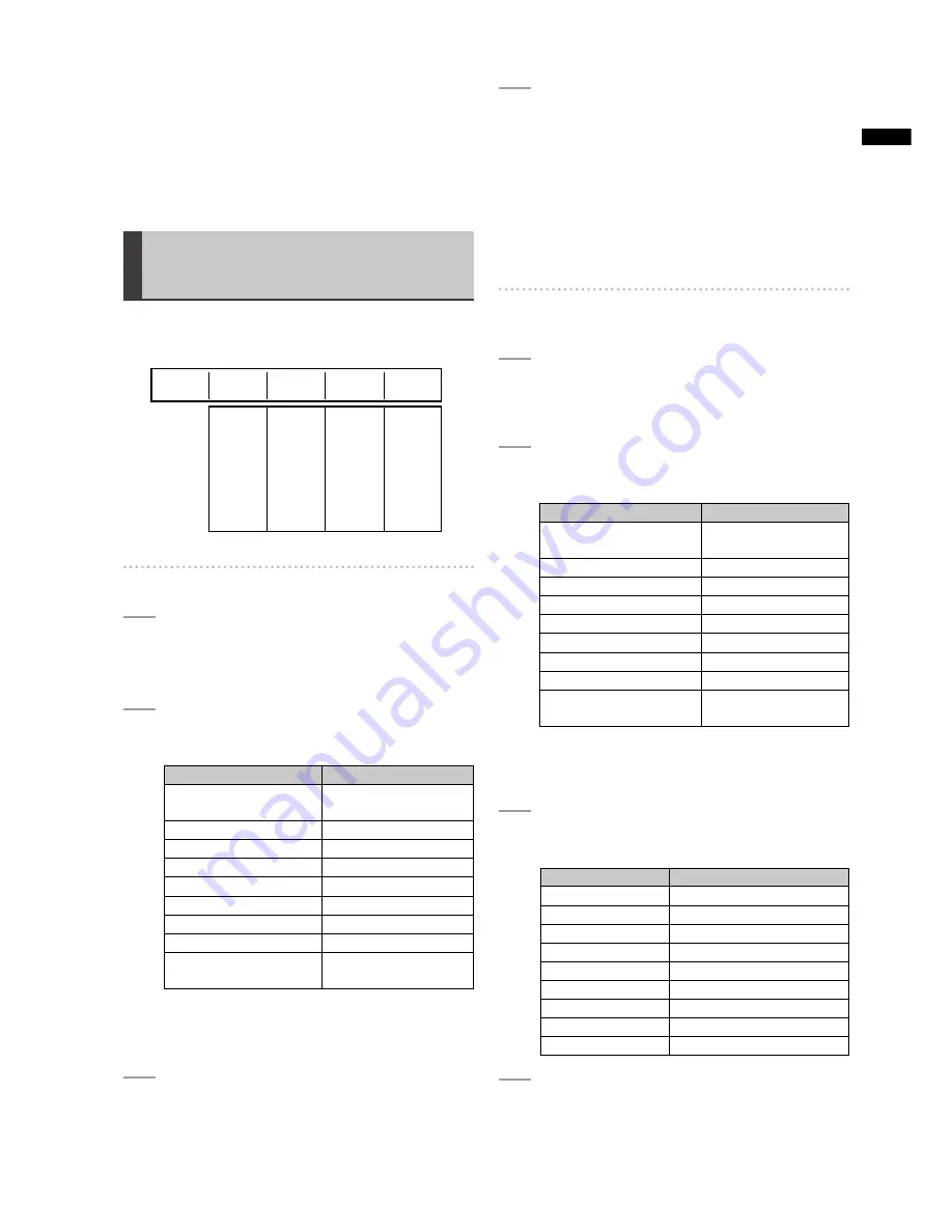
background image

29

Basic Oper

ation

Use the rotary 1 control to set the internal video output type 

TOBACKMATTEVIDEO;"!#+-!44%= ORCOLORBAROUTPUT
;#/,/2"!2=

)F;-%-/29=ISSELECTEDANEXTERNALVIDEOINPUTSOURCE

can be saved in internal memory and used as internal 
video (

PAGE

Setting the Back Matte 
[BACK MATTE]

4OCREATEBACKMATTEVIDEOASINTERNALVIDEOUSETHE
;"!#+-!44%=SUBMENUOFTHE;).46)$%/=MENU

Rotary 1

Rotary 2

Rotary 3

Rotary 4

Rotary 5

WHITE

YELLOW

CYAN

GREEN

MAGENTA

RED

BLUE

BLACK

CUSTOM1

CUSTOM2

LEVEL

 0-255

SET

 BACK M

 WASH

OFF

H1

H2

H3

V1

V2

V3

DIAG1

DIAG2

0-255

COLOR

BACK

WHITE

MATTE

0

LEVEL

255

PATTERN GRADE

H1

To set the back matte video color

1


To check the back matte video color, press the 
A/PROG INT (or B/PROG INT) button to set the 
currently displayed bus to the internal video.

2


Use the rotary 2 control to set [COLOR] to one 
of the colors shown in the table below.

Setting

Color

;7()4%=FACTORYDEFAULT
SETTING 

White

;9%,,/7=

9ELLOW

;#9!.=

Cyan

;'2%%.=

Green

[MAGENTA]

Magenta

;2%$=

2ED

[BLUE]

Blue

;",!#+=

"LACK

[CUSTOM1] or 
[CUSTOM2]

Grey as the factory 
default setting

The P

B

, P

2

AND9VALUESARESHOWNINTHEJOYSTICK

ANDROTARY:CONTROLSETTINGSAND$DISPLAYDISPLAY

area (

PAGE 

3


If [CUSTOM1] or [CUSTOM2] is selected in 
Step 2, set [SET] to [BACK M] (back matte) 
using the rotary 3 control and set [PATTERN] to 
[OFF] using the rotary 4 control.

4


If [CUSTOM1] or [CUSTOM2] is selected in 
Step 2, use the joystick and rotary Z control to 
set the [P

B

] and [P

R

] values in the range of 0 to 

255 and the [Y] value in the range of 16 to 235 
for selecting the back matte video color.

If other than [CUSTOM1] and [CUSTOM2] is 
selected, set the color level (the Y signal level 
for white) using the rotary 3 control.

To set the color gradation for back matte 
video

1


To check the back matte video color, press the 
A/PROG INT (or B/PROG INT) button to set the 
currently displayed bus to the internal video.

2


Use the rotary 2 control to set [COLOR] to one 
of the colors shown in the table below.

Setting

Color

;7()4%=FACTORYDEFAULT
SETTING 

White

;9%,,/7=

9ELLOW

;#9!.=

Cyan

;'2%%.=

Green

[MAGENTA]

Magenta

;2%$=

2ED

[BLUE]

Blue

;",!#+=

"LACK

[CUSTOM1] or 
[CUSTOM2]

Grey as the factory 
default setting

The P

B

, P

2

AND9VALUESARESHOWNINTHEJOYSTICK

ANDROTARY:CONTROLAND$DISPLAYSETTINGSDISPLAY

area (

PAGE 

3


Set [PATTERN] (gradation pattern) using the 
rotary 4 control.

Setting

Gradation pattern

[OFF]

No gradation

;(=

(ORIZONTALGRADATION

;(=

(ORIZONTALGRADATION

;(=

(ORIZONTALGRADATION

[V1]

Vertical gradation 1

[V2]

Vertical gradation 2

[V3]

Vertical gradation 3

;$)!'=

$IAGONALGRADATION

;$)!'=

$IAGONALGRADATION

4


If [CUSTOM1] or [CUSTOM2] is selected 
in Step 2, set [SET] to [WASH] (wash color 
meaning companion color for gradation) using 
the rotary 3 control.

Содержание AG-HMX100P

Страница 1: ... 1 Note that Operating Instructions Vol 1 describes basic operations of the digital AV mixer For instructions on advanced operations of the digital AV mixer refer to Operating Instructions Vol 2 pdf file contained in the supplied CD ROM Before operating this product please read the instructions carefully and save this manual for future use ...

Страница 2: ...the equipment CAUTION The mains plug of the power supply cord shall remain readily operable 4HE RECEPTACLE MAINS SOCKET OUTLET SHALL BE installed near the equipment and shall be easily accessible To completely disconnect this equipment from the AC mains disconnect the mains plug from the AC receptacle CAUTION In order to maintain adequate ventilation do not INSTALL OR PLACE THIS UNIT IN A BOOKCASE...

Страница 3: ...ectrician for replacement of the obsolete outlet 0ROTECT THE POWER CORD FROM BEING WALKED ON OR PINCHED PARTICULARLY AT PLUGS CONVENIENCE RECEPTACLES AND THE POINT where they exit from the apparatus NLY USE ATTACHMENTS ACCESSORIES SPECIlED BY THE MANUFACTURER 5SE ONLY WITH THE CART STAND TRIPOD BRACKET OR TABLE SPECIlED BY THE MANUFACTURER OR SOLD WITH THE APPARATUS 7HEN A CART IS USED USE CAUTION...

Страница 4: ... THE INSTRUCTIONS MAY CAUSE HARMFUL INTERFERENCE TO RADIO COMMUNICATIONS OWEVER THERE IS NO guarantee that interference will not occur in a particular installation If this equipment does cause harmful interference to radio or television reception which can be determined by turning the equipment off and on the user is encouraged to try to correct the interference by one of the following measures s ...

Страница 5: ...tainers on top of the equipment CAUTION O NOT REMOVE PANEL COVERS BY UNSCREWING them 4O REDUCE THE RISK OF ELECTRIC SHOCK DO NOT remove the covers No user serviceable parts inside 2EFER SERVICING TO QUALIlED SERVICE PERSONNEL CAUTION The mains plug of the power supply cord shall remain readily operable 4HE RECEPTACLE MAINS SOCKET OUTLET SHALL BE installed near the equipment and shall be easily acc...

Страница 6: ...his plug Should the fuse need to be replaced please ensure that the replacement fuse has a rating of 13 amps and that it is approved by ASTA or BSI to BS1362 HECK FOR THE 34 MARK OR THE 3 MARK on the body of the fuse If the plug contains a removable fuse cover you must ensure that it is refitted when the fuse is replaced If you lose the fuse cover the plug must not be used until a replacement cove...

Страница 7: ...NNECTING CABLES 53 Use shielded cables which provide quality performance for high frequency applications as connecting cables s 7HEN CONNECTING TO THE 6 SIGNAL TERMINAL USE A CABLE WITH A FERRITE CORE s F YOUR APPARATUS IS SUPPLIED WITH FERRITE CORE S THEY MUST BE ATTACHED ON CABLE S FOLLOWING instructions in this manual 3 Performance level The performance level of the apparatus is equivalent to o...

Страница 8: ...NS 2 4 0 44 2 23 Setting Video and Audio Input Sources 5 6 24 Setting the Video Format 6 2 4 26 Setting the Bus BUS 27 3ETTING UDIO HANNELS 5 27 Setting the Audio Faders 5 2 27 4 6 ENU NTERNAL 6IDEO 3ETTING Screen 28 3ETTING THE ACK ATTE 44 29 UTPUTTING OLOR ARS 2 2 30 Using Still Pictures or Movies as Internal Video 29 30 Using Video Input from PC PC1 32 Switching or Combining of Video 33 Selecti...

Страница 9: ...CT THE RECORDED IMAGES AND OR sound The liquid crystal parts are highly precise with 99 99 of the pixels effective This leaves less than 0 01 of pixels that may not light or may remain on all the time These phenomena are normal The response speed brightness and color contrast of the liquid crystal parts vary with the operating temperature and s viewing angle PERATE THE 42 34 CONTROL TO GET THE CLE...

Страница 10: ...s for program output 1 and preview output 2 this unit is equipped with multi view connectors USED TO DISPLAY ALL INPUT SOURCES ON THE SAME SCREEN AND 58 CONNECTORS USED FOR VARIOUS OUTPUTS Waveform display ULTI VIEW OUTPUT DISPLAYS WAVEFORMS FOR INPUT SIGNAL CHECK ON THE MONITOR 3D camera supported 4WO PAIRS OF AND 2 CHANNELS ARE AVAILABLE TO INPUT CAMERA VIDEO SOURCES AND CAN BE SWITCHED BETWEEN ...

Страница 11: ...ol 2 27 3ETTING THE EXTERNAL SYNCHRONIZATION s page Vol 2 28 Setting details for connecting PC s page Vol 2 28 Setting for external interface s page Vol 2 28 Selecting video to use PAGE 5SING VIDEO PAGE 6OL Adjusting video s PAGE 6OL DJUSTING MIXING SOUND s PAGE 6OL 3ETTING THE VIDEO SWITCHING TRANSITION EFFECT s PAGE NSERTING KEYING CHARACTERS OR GRAPHICS INTO s video PAGE 3ETTING THE DOWNSTREAM ...

Страница 12: ...Overview Accessories 0OWER CABLE FOR 8 0 FOR 8 2 NOTE Be sure to appropriately dispose of the packing material when you have unpacked the product s Consult your supplier regarding purchase of accessories s ...

Страница 13: ...10 14 6 7 8 21 25 24 27 26 20 18 1 POWER button page 19 2 PROJECTOR REMOTE button pages 18 Vol 2 28 3 ASPECT control and button page 36 4 Joystick pages 20 28 30 34 36 Vol 2 4 Vol 2 6 Vol 2 13 5 Rotary Z control pages 20 28 30 36 Vol 2 13 6 HOLD button pages 34 36 CENTER button pages 34 36 Vol 2 13 SCENE GRABBER button page 36 7 Menu buttons s SETUP button page 22 s INT VIDEO button page 28 s DSK ...

Страница 14: ...IFT button s SOURCE 1 5 2 6 3 7 4 8 buttons s INT button 25 EFFECTS buttons for A PROG and B PRESET buses pages Vol 2 13 Vol 2 15 s STILL buttons page Vol 2 15 s STROBE buttons page Vol 2 15 s VIDEO EFFECTS buttons page Vol 2 13 s COLOR EFFECTS buttons page Vol 2 13 26 PREVIEW buttons page 33 s ME PVW button s A PROG selector button s B PRESET selector button s DSK selector button 27 PATTERN area ...

Страница 15: ...IDEO IN 1 2 connectors For devices and signals which can be connected to EACH CONNECTOR SEE h3YSTEM ONlGURATION XAMPLESv PAGE AND h XAMPLE ONNECTIONS WITH AMERAv PAGES 6OL TO NOTE For the DVI I IN connector and DVI D IN connectors shielded s DVI cables with noise suppression core are recommended For transmitting HD SDI signals via the SDI IN 1 to 4 s connectors and SDI OUT connectors cables equiva...

Страница 16: ...VW SDI OUT AUX DVI D OUT PGM DVI D OUT MULTI VIEW DVI I IN AUDIO IN MIC SDI IN 1 SDI IN 2 SDI IN 3 SDI IN 4 VIDEO IN 1 VIDEO IN 2 SDI OUT MULTI VIEW G L ADV REF Program output Preview output Professional use monitor AUX output Program output Professional use projector Home use television SDI output G L external sync signal 1 Advanced reference signal 1 DVI D output Professional use video camera Pr...

Страница 17: ...sional use projector Home use television Professional use video camera Home use video camera Termi nation P2 mobile Professional use camera Professional use camera System camera MIC Professional use audio equipment PC SDI output G L external sync signal 1 Advanced reference signal 1 DVI D output Loop through SDI video and audio input SDI video and audio input HDMI input HDMI input MIC input Analog...

Страница 18: ...enerator External controller Program output Preview output Professional use LCD monitor Professional use projector Home use television Program output AUX output SDI output DVI D output MIC Professional use audio equipment PC Professional use video camera Home use video camera Termi nation P2 mobile Professional use camera Professional use camera System camera Loop through SDI video and audio input...

Страница 19: ...ED TO MAKE THE SETTINGS AS DESCRIBED BELOW WITH the SETUP menu PAGE AND 4 6 MENU PAGE TO SET UP THIS UNIT Setting the startup mode s PAGE Changing direct patterns s PAGE Setting video and audio input sources s PAGE Setting the video format s PAGE Setting the bus s PAGE Setting the audio output channels s PAGE Setting the audio fader s PAGE 3ETTING THE BACK MATTE VIDEO s PAGE Outputting the color b...

Страница 20: ...MI1 FORMAT NPUT SOURCE OF THE connector is in unavailable format CHANGE HDMI2 FORMAT NPUT SOURCE OF THE connector is in unavailable format Change the system format setting or the input source setting NOTE The FAN STOP error message is also displayed on the multi view screen However since the multi view screen does not open when this unit is in 3D mode page Vol 2 25 no error message is displayed ev...

Страница 21: ...OL 9 2 3ETTING KEY LEARN PAGE 6OL 4 4 9 3ETTING THE TITLE KEY PAGE 6OL 02 4 2 Setting the projector PAGE 6OL To select the menu OR THE 3 450 4 6 3 AND 5 EFFECTS menus press the corresponding menu button For other menus press the operation button related to the settings For more information see the description of each setting in List of Menus If the menu is selected the menu title setting items and...

Страница 22: ...otary 3 Rotary 4 Rotary 5 RESET PRESET FACTORY MODE RESET POWER To reset settings other than basic settings to the factory default settings when the unit is restarted 3ET 0 7 2 TO 2 3 4 RESET MODE USING THE ROTARY control Settings other than SETUP menu settings direct pattern SETTINGS EVENT MEMORY SETTINGS lLE SETTINGS AND KEY LEARN settings are reset to the factory default settings To reset all s...

Страница 23: ...ern button of the pattern you want to change 4HE SELECTED BUTTON mASHES 4 Enter the number of the pattern you want to set for transition or as the key using the numeric keys in the numeric key area 9OU CAN SELECT THE NUMBER FROM 888 888 AND 888 FOR TRANSITION PATTERNS 888 FOR KEY PATTERNS AND TO FOR KEY LEARN 4HE SETTING SCREEN SWITCHES TO THE 2 4 0 44 2 42 3 4 SCREEN OR 2 4 0 44 2 9 SCREEN The en...

Страница 24: ...the following three cases 7HEN THE SYSTEM FORMAT SETTING IS 3 s PAGE 7HEN THE SYSTEM FORMAT SETTING IS s PAGE MODE SETTING IS OTHER THAN s The stored settings are read out each time the system format is changed To display the Audio Video Input Source Setting screen 1 Set INPUT to SETUP using the rotary 2 control and press the key 2 When the message OK appears press the key again 4HE UDIO 6IDEO NPU...

Страница 25: ...NPUT INPUT AND ANALOG INPUT AS THE AUDIO INPUT sources A S 1 to A S 4 using the rotary 5 control NOTE If the system format is set to SD s page 19 HDMI cannot be selected If the system format is set to HD VIDEO cannot be selected You cannot set the combinations of video and audio s input sources shown in the table below The settings are automatically changed to available values When the video input...

Страница 26: ...THE SETTINGS IN THE 4 6 MENU PAGE AND THE TITLE MEMORY SETTING PAGE Rotary 1 Rotary 2 Rotary 3 Rotary 4 Rotary 5 0 7 5 4 3 16 9 480 59i 576 50i 720 50p 720 59p 1080 50i 1080 59i HDMI VIDEO 1080 59i 7 5 SET UP FORMAT 16 9 ASPECT AG HMX100P Rotary 1 Rotary 2 Rotary 3 Rotary 4 Rotary 5 0 7 5 4 3 16 9 480 59i 576 50i 720 50p 720 59p 1080 50i 1080 59i HDMI VIDEO 1080 59i 0 SETUP FORMAT 16 9 ASPECT AG H...

Страница 27: ...AN BE ASSIGNED Rotary 1 Rotary 2 Rotary 3 Rotary 4 Rotary 5 1 8 1 4 1 8 1 4 OFF ON SDI1 SDI2 SDI3 SDI4 CH CH AUDIO SDI1 1 2 ON L CH R CH OSD 1 Set CH to one of SDI1 SDI2 SDI3 or SDI4 SDI inputs 1 to 4 using the rotary 2 control 2 Use the rotary 3 control to select the audio input of the SDI input selected in Step 1 which you want to assign the L channel by setting L CH to the desired audio input n...

Страница 28: ...N THE 29 SUBMENU OF THE 3 450 MENU To set the audio output format and the operation of audio faders 3ET 3 52 TO 0 0 2 53 3 0 53 3 0 0 2 OR 3 0 USING THE ROTARY CONTROL The following table shows the output method and audio input sources assigned to the faders for each setting Setting Output Method SOURCE 1 5 Fader SOURCE 2 6 Fader SOURCE 3 7 Fader SOURCE 4 8 Fader 0 0 2 Sound output of the selected...

Страница 29: ...ack matte using the rotary 3 control and set PATTERN to OFF using the rotary 4 control 4 If CUSTOM1 or CUSTOM2 is selected in Step 2 use the joystick and rotary Z control to set the PB and PR values in the range of 0 to 255 and the Y value in the range of 16 to 235 for selecting the back matte video color If other than CUSTOM1 and CUSTOM2 is selected set the color level the Y signal level for whit...

Страница 30: ... the still picture or movie The page count ratio for the title and still picture or movie CAN BE CHANGED FROM THE 29 SUBMENU OF THE SETUP menu PAGE 6OL 5SE THE 29 SUBMENU OF THE 4 6 MENU TO create and display still pictures and movies F A STILL PICTURE IS CREATED h34 34 v AND THE NUMBER OF pages are displayed in the internal video display area in the upper portion of the Setting screen If a movie ...

Страница 31: ... saved still picture NOTE When the system format is set to 720 no change is given to video due to progressive video even if switching is made between FIELD and FRAME To save movies used as internal video Rotary 1 Rotary 2 Rotary 3 Rotary 4 Rotary 5 1 30 480i 1 30 576i 1 14 720p 1 6 1080i 1 30 480i 1 30 576i 1 14 720p 1 6 1080i REPEAT ONCE WRITE PREVIEW EXIT PAGE MEMORY 1 WRITE FRAME 2 MODE REPEAT ...

Страница 32: ...AN BE INPUT FROM 0 TO THIS UNIT VIA THE 6 connector For using video created on PC it is necessary to allocate THE 6 INPUT TO AN INPUT SOURCE NUMBER IN THE 5 6 SUBMENU OF THE 3 450 MENU IN ADVANCE PAGE The source input from PC is set from the PC1 submenu of the SETUP menu Rotary 1 Rotary 2 Rotary 3 Rotary 4 Rotary 5 ANALOG DIGITAL XGA WXGA SXGA 1080 50p 1080 60p _ _ ON OFF PC1 ANALOG A SET FORMAT S...

Страница 33: ...0 3 CONNECTOR TO CHECK SOUND 4HE OUTPUT FROM THE 3 067 54 CONNECTOR CAN BE CHANGED WITH THE FOLLOWING 02 6 7 BUTTONS ME PVW button 5SED TO CHECK SWITCHING AND COMBINED EFFECTS LLOWS YOU TO CHECK THE SWITCHED IMAGE AND the image currently being switched PAGE OR THE image to be combined and the image currently being combined PAGE A PROG selector button LLOWS YOU TO CHECK THE INPUT PROGRAM INPUT SOUR...

Страница 34: ...sed 5 Process the selected pattern by applying effects including border shadow and trail page Vol 2 3 6 Set the pattern position transition start position using the joystick 0RESS THE 4 2 BUTTON TO TURN ON AND THE PATTERN position is set to the center 0RESS THE BUTTON TO TURN ON AND THE JOYSTICK IS fixed to the current position NOTE There are some patterns for which the position s cannot be adjust...

Страница 35: ... PAGE 6OL 3 Press the key Program Preset Transition Program preset transition is an effect of switching from PROGRAM VIDEO BASE VIDEO TO PRESET VIDEO VIDEO USED AS AN EFFECT AND VICE VERSA T IS EXECUTED IN THE SAME METHOD AS DESCRIBED IN h 4RANSITIONv EXCEPT FOR SETTING 490 TO 02 02 IN 3TEP 4HE 7 9 BUTTON IS DISABLED BECAUSE IT LIMITS THE switching direction only from preset video to program video...

Страница 36: ... BACK OF 6OLUME 7 Set the transition time from combining start to end page 35 8 Slide the transition lever to the B side or A side or press the AUTO TAKE button 7HEN THE 54 4 BUTTON IS PRESSED IT IS LIGHTED and source video A is combined with B or source VIDEO IS COMBINED WITH To use the Scene Grabber function 0RESS THE 3 2 2 BUTTON TO TURN ON The scene grabber function allows you to move the imag...

Страница 37: ...button 4HE BUTTON IS LIGHTED AND mASHES WHILE THE KEY IS being inserted To use a transition pattern as DSK 0RESS THE 3 43 BUTTON TO TURN ON AND SELECT a transition pattern instead of selecting preset video PAGE The dissolve effect is applied NOTE It is impossible to use a pattern other than transition patterns for DSK If a pattern unavailable for DSK is selected the DSK EFFECTS button flashes To s...

Страница 38: ...xecution button again The button goes off and fade in is executed To synchronize the audio faders to the transition lever 0RESS THE 5 7 6 BUTTON TO TURN ON To set the FADE transition time 4HE CURRENTLY SET TRANSITION TIME 4 IS shown in the area where the event number transition time pattern number and internal video are displayed on the setting screen PAGE The factory default setting is 02 00F SEC...

Страница 39: ...HED ON s RE THE CABLES CONNECTED CORRECTLY s AS FADE HAS BEEN APPLIED s AS THE SOURCE BEEN INPUT CORRECTLY s There is no color s S THE VIDEO EFFECT OR COLOR EFFECT SET TO s S ONLY COMPONENT 9 SIGNAL PROVIDED AS INPUT INSTEAD OF THE COMPOSITE SIGNAL s AS THE SOURCE BEEN INPUT CORRECTLY s There is no sound s AS AUDIO FADE OUT BEEN APPLIED s AS THE SOURCE BEEN INPUT CORRECTLY s The image does not cha...

Страница 40: ...SED IN WHOLE SYSTEM VIDEO Sampling frequency 3 FORMAT 9 Z 0B 02 Z FORMAT 9 Z 0B 02 Z I P 0S 9 Z 0B 02 Z I P Video format 3 I I P P I I 0S FOR VIDEO ONLY 1UANTIZATION 10 bits Internal processing 4 2 2 4 12 bits AUDIO Sampling frequency K Z DIGITAL INPUT SYNCHRONIZES WITH VIDEO SIGNAL 1UANTIZATION NALOG INPUT BITS 3 INPUT BITS INPUT BITS Frequency response n D TO D AT Z TO K Z ANALOG n D TO D AT Z T...

Страница 41: ...IGNAL OMPLYING WITH 3 04 STANDARDS 6 X 4 3 SINGLE LINK INCOMPATIBLE WITH 0 MODE 2 CHANNEL SIGNAL FOR 3 9 3 SIGNAL FOR Advanced reference output 6 2 BNC x 1 75 7 Analog composite signal 3YNC 6 P P 43 6 P P 0 URST 6 P P 43 6 P P 0 AUDIO INPUT OUTPUT UDIO INPUT 5 8 2 SETS PAIR OF AND 2 n D U SWITCHABLE BALANCED K7 3 MBEDDED UDIO SETS 3 SERIAL DIGITAL SIGNAL OMPLYING WITH 3 04 AND 45 2 4 standards SER...

Страница 42: ...ormat VIDEO SDI HDMI DVI D DVI I NTSC 9ES PAL 9ES I 9ES 9ES P 9ES I 9ES 9ES P P 9ES 9ES 9ES P 9ES 9ES 9ES I 1 9ES P OVER I 9ES P OVER I 9ES I 9ES 9ES 9ES I 9ES 9ES 9ES 1 4REATED AS I Format VIDEO SDI HDMI DVI D DVI I Z 9ES 1 Z 9ES Z 9ES Z 9ES Z 9ES Z 9ES 1 F IS SELECTED THE INPUT SIGNAL IS OUTPUT AS IS FROM THE 6 54 CONNECTOR DISABLING THE 6 MIXER functions including video switching effects ...

Страница 43: ...D DVI I NTSC PAL I P I P P 9ES P 9ES I 1 0S 9ES P OVER I 9ES 0S 9ES P OVER I 9ES 0S 9ES P OVER I 9ES I 9ES I 9ES 1 4REATED AS I Inrush current measured according to European standard EN55103 1 15 A Mass and dimensions are approximate values Specifications are subject to change without notice ...

Страница 44: ... EY EARN 5 Pattern edge 5 3 0 44 2 9 MENU 5 2 2 7 8 9 02 3 4 BUS SOURCE SELECTOR BUTTONS 14 24 INT button 14 3 4 BUTTON 14 3 52 BUTTONS 14 02 3 4 SELECTOR BUTTON 14 33 BUS 27 Bus setting 27 C 4 2 BUTTON 13 34 36 13 HROMA KEY 6 Border 7 Color canceling 6 Cropping 7 Effects 7 EY SETTING 6 2 9 BUTTON 14 6 2 9 MENU 6 2 2 30 Color bar output 30 2 6 2 43 BUTTONS 13 2 43 MENU 13 Colors of video adjusting...

Страница 45: ...e operations 19 G 28 CONNECTOR 15 16 18 24 28 TERMINAL 15 GPI connector 15 26 GPI control of video effects 26 Gradation 29 H CONNECTORS 15 17 18 VIDEO PROCESSING SYSTEM CONlGURATION 17 BUTTON 13 34 36 OURS METER 26 I Initial setup 19 Input sources 33 Setting 24 Internal video 33 Setting screen 28 4 6 BUTTON 13 28 4 6 MENU 28 J OYSTICK 13 20 28 30 34 36 4 6 13 K 9 6 8 EYING 35 EY EARN 9 9 2 9 L CON...

Страница 46: ...en 20 Setup 22 Operation screen 22 SETUP button 13 22 SETUP menu 22 26 3HADOW 3 7 4 3 4 KEY 14 27 28 30 32 33 4 9 10 13 15 3 52 FADERS 14 27 Startup mode 22 Still 15 STILL buttons 15 Still pictures displaying 31 Still pictures saving as internal video 31 Strobe 15 342 BUTTONS 15 3934 26 3934 26 System configuration examples 16 System settings 26 T 4 9 CONNECTOR 15 29 Time display 26 Time effects 1...

Страница 47: ...MEMO 47 ...

Страница 48: ... waste in accordance with national legislation For business users in the European Union If you wish to discard electrical and electronic equipment please contact your dealer or supplier for further information Information on Disposal in other Countries outside the European Union This symbol is only valid in the European Union If you wish to discard this product please contact your local authoritie...

Отзывы: