background image

Содержание AG-7700E

Страница 1: ...ng Instructions SVAS HiFi Video Cassette Recorder Player vodet ac UD 7 diss ao l SUD Panasonic Before attempting to connect operate or adjust this product please read these instructions completely VQT...

Страница 2: ...USE SHOULD BE REMOVED AND THE PLUG CUT OFF AND DISPOSED OF SAFELY THERE IS A DANGER OF SEVERE ELECTRICAL SHOCK IF THE CUT OFF PLUG iS INSERTED INTO ANY 13 AMP SOCKET If a new plug is to be fitted plea...

Страница 3: ...ion CAUTION TO REDUCE THE RISK OF FIRE OR SHOCK HAZARD AND ANNOYING INTERFERENCE USE THE RECOMMENDED ACCESSORIES ONLY eLa Soci t PANASONIC FRANCE importateur du Dit model is onderworpen aan de EEG ric...

Страница 4: ...lear pictures with high resolution Highly dependable mechanisms A full array of such highly reliable mechanisms as the Al servo driven large diameter capstan dual reel motor drive system and DD cylind...

Страница 5: ...g AG 7700 only E 26 AUTO CUT OUT editing simple automatic editing AG 7700 only E 27 Split editing AG 7700 only essere eters E 29 Precautions for editing AG 7700 only ss err E 30 Using the dial menu fu...

Страница 6: ...Hi Fi audio CH2 AG 7700 only 2 Function display lamp area WIDE lamp ses reece eee Lights during WIDE signal recording and WIDE tape playback Cassette in lamp He Lights when a cassette is loaded S VHS...

Страница 7: ...LAY button AG 7700 only PAUSE STILL button sss ese Establishes still picture mode during playback and pause mode during recording EJECT button so ects Ejects cassette REW PAGE DOWN button Rewinds the...

Страница 8: ...only RESET button ss essere reer Resets counter CTL TC UB button sse ere Switches counter mode LTC AUTO VITC buitton Switches time code read mode ON SCREEN button e e 0 Displays data on monitor TV Fu...

Страница 9: ...Aad a wae ea Hour meter display The sel items are indicatedcaleba while the RESET button is kept depressed Counter Display i Set the CONTROL and Capstan rotation a cumulative time L A I tI rf DIAL MOD...

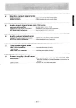
Страница 10: ...p through 75 Q termination switch LINE IN connector e seers Video signal input connector with loop through 75 Q termination AG 7700 only switch 2 Video output signal area 1 VIDEO OUT 1 2 connectors 1...

Страница 11: ...ound only Audio output signal area NORM Hi Fi audio output connectors NORM Hi Fi audio CH1 2 output connectors Hi Fi audio output connectors Output connectors for hi fi sound only Time code signal are...

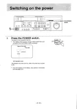
Страница 12: ...y below appears through VIDEO MONITOR OUT connector if the ON SCREEN button is pressed Types of time data Time data CTL 0 00 00 00 VTR operation mode This appears only when item No 4004 of the dial me...

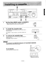
Страница 13: ...push the center area of the cassette gently i ee ee The cassette in lamp now lights in the function display lamp 0 o area 3 Toremove the cassette tape Press the EJECT button Draw the emerging cassette...

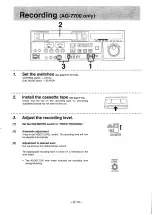
Страница 14: ...ecording level 1 Set the CH2 METER switch to VIDEO TRACKING VIDEO TRACKING T AUDIO 2 Automatic adjustment CHD Press in the VIDEO LEVEL control The recording level will now CH METER be adjusted automat...

Страница 15: ...ITER item No 3002 dial menu function a The dial menu functions are used to activate the audio limiter function and Dolby NR system see page E 36 When the audio limiter function is activated the automa...

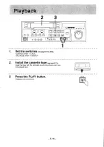
Страница 16: ...3 s CONTROL switch LOCAL DIAL MODE switch SEARCH 2 Install the cassette tape see page E 13 Install the tape with the recorded sound and pictures which are to be played back ia Ty 3 Press the PLAY butt...

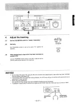
Страница 17: ...lects to the maximum NOTES Set the Dolby NR system ON using the dial menu function when playing back a tape which has been recorded using the system see page E 36 f the tracking shifts out of alignmen...

Страница 18: ...n during recording or playback PAUSE STILL During playback the unit is placed in the PAUSE STILL mode and still pictures are played back e During recording the unit is placed in the REC PAUSE mode and...

Страница 19: ...the normal speed depending on the speed at which the inner dial is turned When the turning of the dial is stopped a still picture display appears regardless of the switch setting 2 SHUTTLE mode in res...

Страница 20: ...pe automatically stops when the tape counter display nears the 0 00 00 00 mark or NOTE M The AUTO STOP function does not work when e The CONTROL switch is at the REMOTE position The CTL TC UB button i...

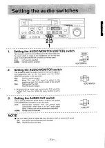
Страница 21: ...2 sound is output to the a headphones jack CH1 sound is heard at the left and CH2 CH2 sound at the right AUDIO MONITOR The CH2 sound is output No sound will be heard from normal audio CH2 when the AUD...

Страница 22: ...EVEL control AG 7700 only This is used to adjust the video level automatically during recording LEVEL PUSH The video level is automatically adjusted wom PULL The video level is not automatically adjus...

Страница 23: ...tch This is used to set the unit s control mode REMOTE Set to this position for operating the unit by remote REMOTE control using an controller etc Only the unit s eject Eu if function will now be ope...

Страница 24: ...RACKING control on the source unit so that the TRACKING meter pointer deflects to its maximum 3 Set the TRACKING control on the editor to its center clickstop position 4 Set the FRAME SERVO item No 60...

Страница 25: ...Select the editing mode Assemble editing Press the ASSEMBLE button When it is pressed once the button lights when it is pressed again its light goes off Insert editing Select the INSERT VIDEO AUDIO CH...

Страница 26: ...counter display shows OFFa _ 9 00 00 00 ey MEMORY 3 Find the edit start point by conducting a search operation and place the unit in the still picture mode Refer to page E 19 for details on search op...

Страница 27: ...f the button causes one of the function indicator lamps CTL TC or UB to light 3 Find the edit end point by conducting a search operation and place the unit in the still picture mode VEN Refer to page...

Страница 28: ...ton while pressing down the EDIT button The tape jogs back automatically for about 3 seconds and editing commences When colour framing for about 5 seconds 8 End of editing When the tape counter reache...

Страница 29: ...t edited ce viDES ee cual ks ene 2 _ omX ry y 1 3 Press the AUDIO CH1 button again VIDEO CH1 CH2 The insert editing of the AUDIO CH1 sound is terminated al 2S os ry NOTES The editing mode cannot be sw...

Страница 30: ...is possible with a 3 second preroll time by using an external sync signal EXT M However since the external sync signal cannot be used during colour framing editing editing cannot be conducted if the...

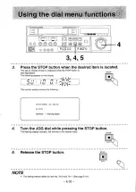
Страница 31: ...O connector The monitor display shows the following __ SETUP MENU NO 1001 01 SYNC Flashing display 02 STILL TIME SELECT 03 TAPE PROTECTION 04 READY OFF MODE SELECT 05 DIRECT SEARCH 06 SHORT FF 07 AUTO...

Страница 32: ...n the display mot Ft Ft awit thet tf The monitor display showns the following SETUP MENU NO 1001 00 01 SYNC NORMAL Flashing display 4 Turn the JOG dial while pressing the STOP button The flashing disp...

Страница 33: ...e normal counter indication 8 Return the DIAL MODE switch to SEARCH The normal screen is returned SEARCH f the switch is returned to SEARCH without the SET button MENU having been pressed in step 7 th...

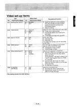
Страница 34: ...CT setting elapses the tape is advanced three frames and the unit enters the READY OFF mode ap proximately 30 minutes later Selects the operation in the READY OFF mode 00 Drum rotates due to loose tap...

Страница 35: ...7700 2004 2005 WIDE MODE SELECT 00 02 PB EE PB EE SELECT ac Gt JERR ee AUTO 01 WIDE NORMAL Sets the image that appears on the screen when the unit is in the STOP mode 00 The playback image is output...

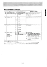
Страница 36: ...REC Selects the Hi Fi recording setting eer rorenly ho OR ce 00 Only normal audio is recorded no Hi Fi audio is recorded 01 Both Hi Fi and normal audio are recorded 3004 HI FI INPUT SELECT HI Fl INPU...

Страница 37: ...e while opserving superimpose Selection is made while Selects horizontal position for VIDEO MONITOR superimpose display moves characters to right as No is increased Selects vertical position for VIDEO...

Страница 38: ...ting S VHsib ci OTHER TYPES HEOADING EEO UNLOADING E 38 Selects ID code returned to 9P device type Description of function Enables or disables operation of panel EJECT STOP button in remote mode 00 En...

Страница 39: ...gsopyage ON The shading denotes the initial setting 15 FRAME 100 Set to this position when signals not in COLOUR FRAME se Selects play delay time during play start from 0 to 15 frames Sets framing mod...

Страница 40: ...ot be selected Avoid selecting an adjoining line VITC POSITION SEL 2 AG 7700 only Selects VITC signal insertion line Same line as No 7004 cannot be selected 12 LINE Avoid selecting an adjoining line 2...

Страница 41: ...ects the response method used to return the VITC CTL interpolation value from 9P in response to CURRENT TIME SENSE 00 HOLD_VITC 74H 16H is returned 01 INTERPOLATED LTC 74H 14H is returned 7010 7011 se...

Страница 42: ...VITC is recorded in the vertical blanking period of the video signals so that even without using the normal audio C2 track it is used to record the information regarding position on the tape and user...

Страница 43: ...Priority is given to reading out the VITC signal when in the slow mode and to reading out the LTC signal at all other times VITC VITC Only the VITC signal is read out Interpolation is provided by the...

Страница 44: ...the continuous time code on the editing tape Set the TC INT EXT SELECT item No 7001 dial menu function to INT See page E 40 Set the TC MODE item No 7002 dial menu function to REGEN See page E 40 e Se...

Страница 45: ...signal when in the slow mode and to reading out the LTC signal at all other times VITC Only the VITC signal is read out Interpolation is provided by the CTL signal when it is no longer possible to re...

Страница 46: ...r value LTCR Playback value of LTC time code VTCR Playback value of VITC time code ETCG External time code generator value LUBG Generator value of LTC user s bit VUBG Generator value of VITC user s bi...

Страница 47: ...on reverse direction Block 4 AG 7700 only The edit modes are indicated as follows ASM Assemble V12 Insert VIDEO AUDIO CH1 AUDIO CH2 NOTE The block 3 4 display and wide indication appears only when the...

Страница 48: ...e SYNC item No 1001 dial menu function to NORM Set the AUDIO CH2 item No 3006 dial menu function to AUDIO Set to LTC for editing with the LTC time code signal AG 7700 only i i lo of an Color video cam...

Страница 49: ...rce unit Dial menu function SYNC item No AUDIO cable 1001 to NORMAL S VIDEO cable 4P Dial menu function IMAGE item No 2001 to EDIT Main setting editor INPUT switch to S VIDEO iM ee al efeabblin iil Di...

Страница 50: ...Sit oan 4 aA lee OS Oe gas Ea omne PLAYER Sync signal generator Audio signals Video signals BNC 4P S VIDEO AG A800 Remote 00 Haas fa BeOS RUS EDITOR System composed of one editor and two players enabl...

Страница 51: ...set up No 01 When using a controller made by Panasonic Set to OTHER TYPES SETUP NO 00 when the AG A800 Ver 2 00 2 52 is used 3 Set the CONTROL switch to REMOTE 4 Operate the unit from the editing con...

Страница 52: ...n Set the preroll time of the editing controller to 7 SEC Use a colour framed tape in the editor unit e Use a colour programme tape in the source unit This tape need not be colour framed Notes for Col...

Страница 53: ...monitoring Ci o wna Set the INPUT switch to YC for a component or 0 O ul YC input and to LINE for O a VIDEO IN input I ae wi Set the CONTROL switch to LOCAL The above system employs the model AU 65H...

Страница 54: ...section an Malfunction in Turn off the power and switch it back on again and o solenoid section check that the unit operates normally Contact your authorized dealer ifthe unit does not function norma...

Страница 55: ...king been adjusted properly No tape fast forwarding or rewinding No recording or editing AG 7700 only Playback accompanied by noise Striping appears on part of picture during normal playback No colour...

Страница 56: ...nce signal The relationship between the SYNC dial menu function item No 1001 and servo reference signal during normal playback and recording is as described below EXT During playback or search OO erne...

Страница 57: ...inno Deseripion of sonal 2 TRANSMITA 3___ RECEIVE RECEIVE COMMON SPARE TRANSMIT B 2 fen SCS 4 5 6 7 S AUDIO IN OUT connectors XLR Jescription of signal E 5 7...

Страница 58: ...rack ess W Be sure to install a ventilation fan air volume of about 3 3 m 2 sec on the top of the rack Installation of slide rails Use a complete slide rail and bracket unit for 457 mm length part No...

Страница 59: ...adaptor Model No 34 pin Remote Connector Model No Cassette tapes AG C71 5m AG C70A 3m AG C71A 5m AG A800 AG A770 AG A350 AG M730 AG 1A834 This unit is designed as a product which is required to demons...

Страница 60: ...cabinet With stubborn stains or dirt dilute some dish washing liquid allow a cloth to soak in it and then wring it out and clean After having removed the stains or dirt use a dry cloth to wipe away a...

Страница 61: ...ne Hi Fi XLR Line NORM XLR MIC Time code BNC Line Hi Fi XLR Line NORM XLR Headphones 1 4 Monitor RCA Time code BNC Output Track Number S N Ratio Hi Fi dynamic range Audio Frequency Response More than...

Страница 62: ...on von auBerst zuverlassig arbeitenden mechanischen Einrichtungen zu denen ein grofdimensionierter Capstan mit Al Servoantrieb ein doppelter Spulenmotorantrieb sowie eine Direktantriebs Kopftromme geh...

Страница 63: ...nuti Videocassetta NV E180 35 80 5 C 35 C durante ilfunzionamento 424x131 5x415 mm 11 5 Kg circa Sistema PAL 625 righe 50 semiquadri Linea BNC 1 0 Vp p 75 Q S VIDEO 4P Y 1 0 Vp p 75 Q C 0 3 Vp p 75 Q...

Отзывы: