


8
1690 Corporate Circle, Petaluma, CA 94954 • www.panamax.com
FEATURE DETAILS
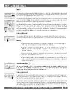
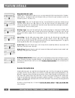
High-Current Outlet Bank
The two high-current outlets allow amplifiers and powered subwoofers to perform to their full potential. When the movie
thunders with a terrific explosion or when the music reaches a climactic crescendo, an amplifier has to rapidly draw large
amounts of current to replenish its power supply capacitors. Traditional line conditioners impede this current draw, in effect,
starving an amplifier and resulting in a flat, dead sound. The High-Current Outlet Bank provides clean, filtered power to
amplifiers but has no current-limiting components to impede performance.
The high-current outlets are designed with a turn-on delay option of 0, 10 or 30 seconds. The 3-position, High-Current
Outlets Turn-On Switch on the back of the MAX
®
5510 is used to select the desired time delay. When a delay is selected,
the high-current outlets will turn on after the isolated outlets and turn off before the isolated outlets (if they are not set to
Always-On). With a delay, the connected equipment will not power up simultaneously, thus preventing loudspeaker noises
such as “thumping”. See the
Sequential Startup/Shutdown
section for more information.
Voltage Sense Triggers
This feature provides two ON/OFF triggers for the MAX
®
5510 using a 12VDC remote control signal. Many components
such as pre-amplifiers and receivers have a 12VDC trigger built in, and will transmit a constant power signal when turned
on and in use. This power signal will initiate the startup or shutdown sequence of the MAX
®
5510’s switched outlets. An
AC Adapter of the appropriate voltage, plugged into a switched outlet on the receiver, may also be used if a 12VDC trigger is
not built in.
The MAX
®
5510 Voltage Sense Trigger input uses standard 3.5 mm mono mini-plug jacks. These jacks have electrically
isolated switches built in. If nothing is inserted into the input jacks, the voltage sense is bypassed and the MAX
®
5510
Switched Outlets button on the front panel controls the startup/shutdown sequence. If a plug is inserted into either one of
the input jacks, the voltage sense becomes the startup/shutdown trigger.
Please note: The Switched Outlets pushbut -
ton on the front panel must be left in the “ON” position if you are using a DC trigger.
The DC Voltage Trigger indicator LED (on the front panel) indicates the status of the Voltage Sense Triggers. When at least
one 3.5 mm mono mini-plug is connected to the voltage sense input jacks and a DC voltage signal is present, the LED will
light to indicate that the voltage sense circuit is ON and the MAX
®
5510’s switched outlets are ON. When the source com-
ponent is turned off and there is no DC signal, the indicator LED will also be off.
Circuit Breakers
There are two separate circuit breakers on the back panel of the MAX
®
5510. The main circuit breaker will trip only if the
total current draw exceeds the maximum current rating (15A). This means that, collectively, all loads must draw more than
15 Amps before the circuit breaker will trip. There is also a 4 Amp circuit breaker to protect the 500 VA Isolation Transformer
and its circuitry. The Isolation Transformer provides pure power for digital source components, which require very little cur-
rent to operate at peak performance.
Please note:
Do not plug high-powered amplifiers or powered subwoofers
into the Isolation Transformer Outlets. Their current requirements may exceed the 4 Amp limit and cause the
circuit breaker to trip.