•
Rotation of work table : Loosen table locking handle (Ref. No.
18) and rotate table (Ref. No. 13) to desired position and
retighten handle.
•
Tilting work table: Loosen table bolt (Ref. No. 10). Remove pin
and nut (Ref. No. 9). To do this, tighten nut until pin slips out easi-
ly. Tilt table to desired angle up to 45° and retighten table bolt.
Reinsert pin and nut when returning the table to 0° position.
•
To obtain more distance between chuck and table, the work
table can be rotated 180° and base can be used as a work sur-
face. This permits drilling of larger objects.
•
Clamp table securely after adjustments have been made.
DEPTH STOP ADJUSTMENT
Refer to Figure 8.
To control drilling depth, use scale (Ref. No. 16) to adjust to desired
depth. Depress and hold pin, slide depth stop nut (Ref. No. 15)
along lead screw until bottom edge of nut coincides with the
desired depth on the scale, then release pin. Use this feature to drill
more than one hole to the same depth.
MOUNT DRILL BIT
Refer to Figure 8.
WARNING:
Be sure drill press is turned off and is disconnected
from power source before adjusting speeds.
•
Place drill bit in jaws of drill chuck.
•
Tighten chuck with drill chuck key. Be sure to tighten the chuck
using all three key positions on the chuck body and remove
chuck key.
•
Use only the self-ejecting chuck key (Ref. No. 31) supplied with
this drill press, or a duplicate key. Use of any other key might
allow start up with the key still in the chuck. An airborne key
could strike the operator and cause injury.
REMOVE THE CHUCK
Refer to Figures 8 and 9.
•
Rotate quill feed handle (Fig. 8, Ref. No. 34) until slot is exposed
in the side of the quill (Fig. 8, Ref. No. 24). Lock quill in position
using handle (Fig. 9, Ref. No. 30).
•
Rotate spindle until inner slot is aligned with outer slot. You will
see through spindle when slots are properly aligned.
•
Insert the drift key (Fig. 8, Ref. No. 25) into the slots and tap
lightly with hammer. The arbor and chuck will drop from spindle.
DIGITAL DISPLAY PANEL
Refer to Figure 6.
•
Display panel ‘A’ shows the depth of the spindle and spindle
RPM.
•
Button ‘B’ turns power on and off to Display ‘A’.
•
Button ‘C’: Press once for spindle depth in inches; press again
for spindle depth in mm; press once again for spindle RPM.
•
Button ‘D’ resets display at zero for spindle depth.
6
3476
2362
1660
566
497
344
257
in/mm
5/16
7.9
5/8
15.9
7/8
22.2
1
1
⁄
4
31.8
1
1
⁄
4
31.8
1
5
⁄
8
41.3
2
50.8
in/mm
3/16
4.8
3/8
9.5
1/2
12.7
3/4
19.0
3/4
19.0
7/8
22.2
1
25.4
in/mm
11/64
4.4
11/32
8.7
15/32
11.9
11/16
17.5
11/16
17.5
3/4
19.0
—
—
in/mm
5/32
4.0
5/16
7.9
7/16
11.1
5/8
15.9
5/8
15.9
13/16
20.6
—
—
in/mm
7/64
2.8
1/4
6.4
11/32
8.7
1/2
12.7
1/2
12.7
5/8
15.9
—
—
in/mm
3/32
2.4
5/32
4.0
1/4
6.4
3/8
9.5
3/8
9.5
1/2
12.7
—
—
in/mm
1/16
1.6
1/8
3.2
3/16
4.8
5/16
7.9
5/16
7.9
7/16
11.1
9/16
14.3
in/mm
1/32
0.8
1/16
1.6
1/8
3.2
1/4
6.4
1/4
6.4
3/8
9.5
1/2
12.7
RPM
Wood
Zinc Diecast
Alum. & Brass
Plastic
Cast Iron &
Bronze
Steel - Mild &
Malleable
Steel - Cast &
Med. Carbon
Steel -
Stainless
& Tool
E
D
C
B
A
Z
Y
X
W
5
4
3
2
1
Motor
Spindle
138
257
304
344
461
497
566
708
755
927
1491
1660
1761
2362
2444
3476
A1-5Z
B2-5Z
A1-4Y
C3-5Z
D4-5Z
A1-3X
B2-4Y
A1-2W
C3-4Y
B2-3X
E5-4Y
D4-3X
C3-2W
D4-2W
E5-3X
E5-2W
RPM
Belt
Location
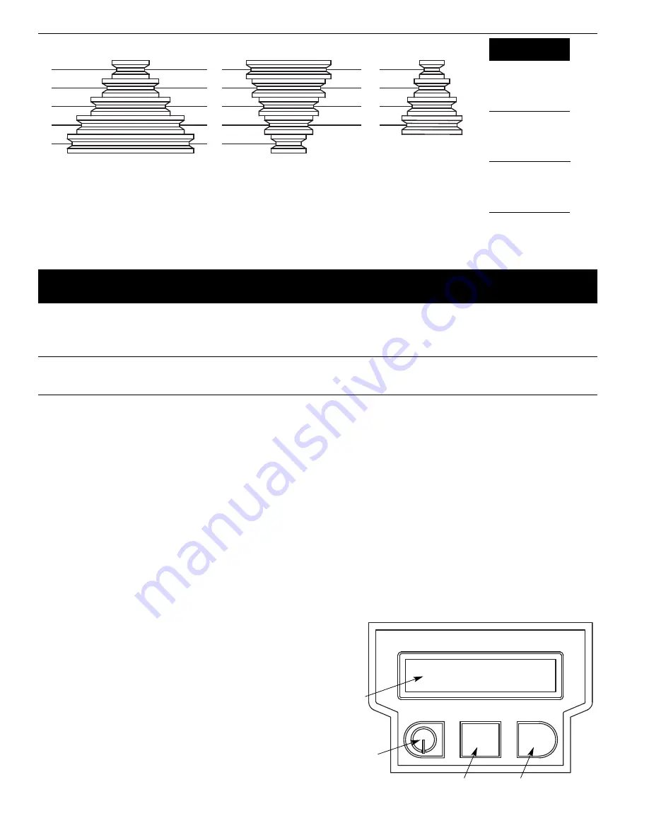
Figure 5 – Spindle Speed Adjustment
Figure 6 – Digital Display Panel
ZERO
UNITS
A
B
C
D
0.000
mm
Palmgren Operating Manual & Parts List
80155 and 80156


