6
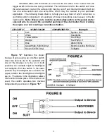
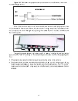
Figure "C"
illustrates the proper hookup of wires to an on/off switch, which will
control a single device.
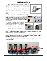
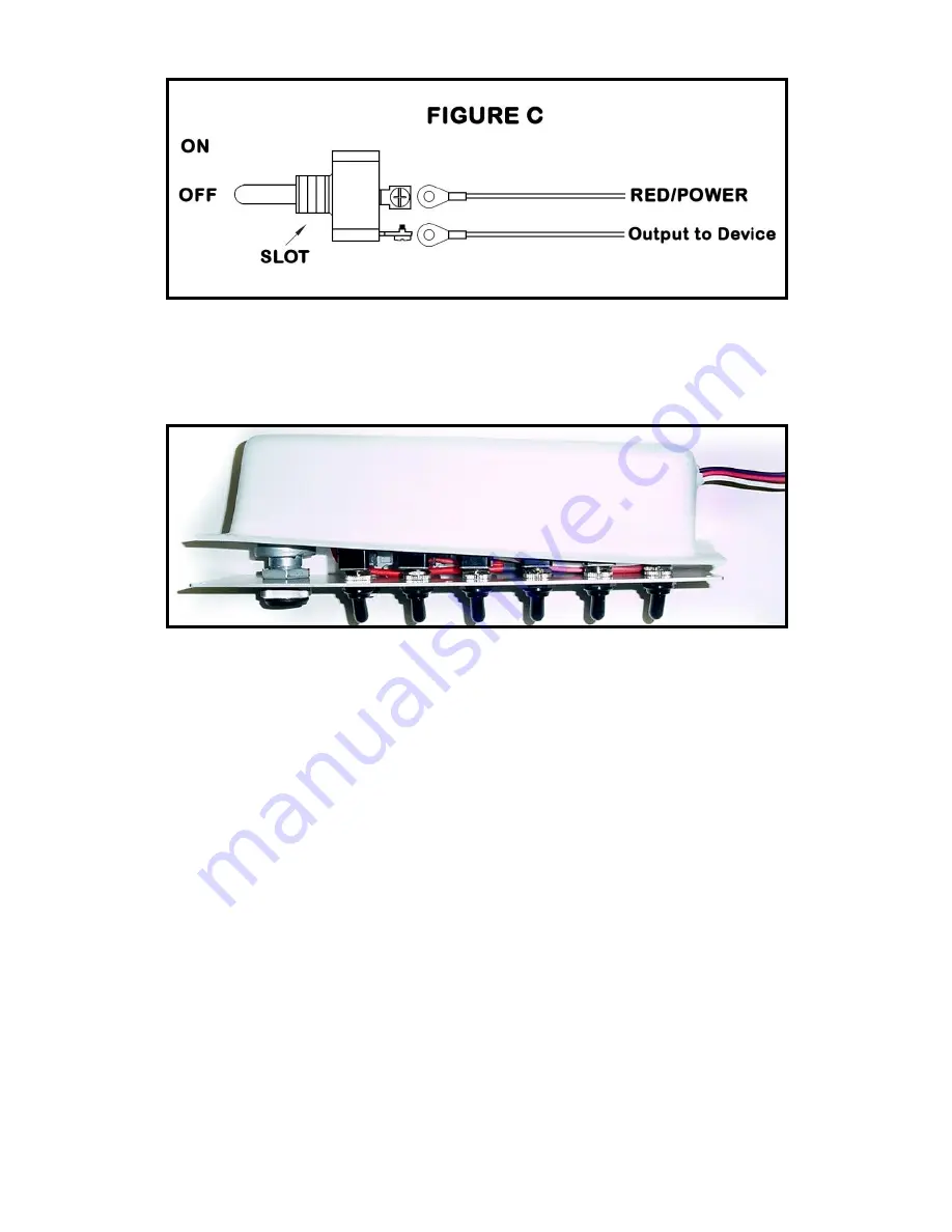
Once all of the wires have been connected to the switches, the polyethylene liner
can be installed. First decide where the wires will be exiting and make a small hole in the
liner and pass the wires through the opening, then slide the liner over the switches and
flush to the panel.
For dash mounted panels, you must cut a
7
¼” x 2 ¼”
opening for the four switch
panel or a
9
¾” x 2 ¼”
opening for the six switch panel to allow room for the polyethylene
liner.
The plastic wire ties are for looming and securing the wires to the vehicle.
The label sheet included is to identify each switch of its function. Simply peel off the
label needed and place it under the switch wired for that function. The "R" and "L"
labels are for right and left in the event an on/off/on switch is turned sideways for turn
signals

