background image

Disassembly Manual EasyNote J2 series

Page 7 of 15

Figure 10

Mainboard

1. Remove 2 x E screws from the Rear of the unit.
2. Remove 2 x A screws from the Battery Connector Bracket and remove it.

Figure 11

3. Remove 2 x F hexbolts from the VGA Connector (right side of unit).

Figure 12

Содержание T19

Страница 1: ...Disassembly Manual EasyNote J2 series Page 1 of 15 Disassembly Manual T19 version change by date 0 1 Copied text from written notes DE 18 10 2005 0 2 Added photos corrected layout DE 19 10 2005 ...

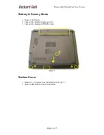
Страница 2: ...es Page 2 of 15 Battery Dummy Cards 1 Remove the Battery 2 Take out the dummy Memory Card 3 Take out the dummy PCMCIA Card Figure 1 Bottom Cover 1 Remove 3 x A screws from the Bottom Cover fig 1 2 Slide out the Bottom Cover as indicated ...

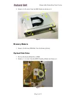
Страница 3: ...mbly Manual EasyNote J2 series Page 3 of 15 Figure 2 Hard Disk Drive 1 Remove 3 x A screws 2 Slide out the Hard Disk Drive HDD Assembly 3 Remove 1 x A screw from the HDD Mounting Bracket and remove it Figure 3 ...

Страница 4: ...move 4 x B screws from the HDD Bracket and remove it Figure 4 Memory Module 1 Remove the Memory DIMM s from the Memory Slot s Optical Disk Drive 1 Push out the Optical Disk Drive ODD 2 Remove 1 x A screw from the ODD Mounting Bracket and remove it Figure 5 ...

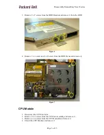
Страница 5: ...e it from the ODD Figure 6 4 Remove 1 x A screw and 1 x D screw from the ODD Frame and remove it Figure 7 CPU Module 1 Disconnect the CPU Fan Cable 2 Remove 2 x A screws from the CPU Fan Assembly and remove it 3 Remove 4 x A screws from the CPU Heatsink and remove it 4 Unlock the CPU Module and remove it ...

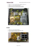
Страница 6: ...oard 1 Remove 2 x C screws from the Video Graphics Accelerator VGA Board 2 Remove the VGA Board 3 Disconnect the VGA Connectors from the VGA Board Figure 9 Keyboard 1 Push up the 3 Clips at the top of the Keyboard to unlock it 2 Flip over the Keyboard and disconnect the Keyboard Flatcable ...

Страница 7: ... Page 7 of 15 Figure 10 Mainboard 1 Remove 2 x E screws from the Rear of the unit 2 Remove 2 x A screws from the Battery Connector Bracket and remove it Figure 11 3 Remove 2 x F hexbolts from the VGA Connector right side of unit Figure 12 ...

Страница 8: ...emove it 5 Remove 4 x A screws from the Mainboard 6 Disconnect the two 2 Flatcables from the Mainboard 7 Slide the Mainboard out of the Bottom Base Assembly Figure 13 Modem 1 Remove 2 x C screws from the Modem 2 Lift up the Modem and disconnect the Modem Cable 3 Remove the Modem and Modem Cable Figure 14 ...

Страница 9: ... the way open 3 Remove 2 x E screws and Grounding Cable from the Left LCD Hinge 4 Remove 2 x E screws and Grounding Cable from the Right LCD Hinge 5 Take away the LCD Assembly and LCD Data Cables Figure 16 LCD Front Bezel 1 Remove four 4 Screw Covers from the LCD Front Bezel 2 Remove 4 x E screws from the LCD Front Bezel 3 Unclip the LCD Front Bezel from the LCD Assembly ...

Страница 10: ...embly 1 Remove 2 x C screws from the Inverterboard 2 Disconnect the Inverterboard Cables 3 Remove the Inverterboard 4 Remove 2 x E screws from the Right Left LCD Bracket 5 Remove the LCD Panel Figure 18 6 Remove 2 x A screws from the Right Left LCD Hinges and remove them ...

Страница 11: ... x C from the Wireless LAN WLAN Board fig 19 2 Disconnect the WLAN Signal Cable and remove it LCD Panel 1 Remove 4 x C screws from the Left LCD Bracket and remove it 2 Remove 4 x C screws from the Right LCD Bracket and remove it 3 Disconnect the LCD Signal Cable from the rear of the LCD Panel ...

Страница 12: ...sembly Manual EasyNote J2 series Page 12 of 15 Figure 20 Bottom Base Assembly 1 Remove 15 x D screws from the Bottom Base Assembly 2 Disconnect the Launch Board Flatcable 3 Disconnect the USB Connector Cable ...

Страница 13: ...clip the Top Cover from the Bottom Base Assembly Figure 22 Top Cover 1 Remove the USB Board Cable 2 Remove 4 x C screws from the Launch Board 3 Disconnect the Speakers Cable from the Launch Board 4 Remove 2 x C screws from the Left Speaker 5 Remove 2 x C screws from the Right Speaker 6 Take away the Speakers ...

Страница 14: ... 23 Touchpad Module 1 Disconnect the Touchpad Cable from the Touchpad Module 2 Unclip the Touchpad Frame in the order shown below 3 Push out the Touchpad Module from the Top Cover Figure 24 Jumpers Dipswitches There are no jumpers or dipswitches in this model ...

Страница 15: ...TAINED HEREIN NOR FOR INCIDENTAL OR CONSEQUENTIAL DAMAGES RESULTING FROM THE FURNISHING PERFORMANCE OR USE OF THIS MATERIAL Copyright 2005 NEC Computers International BV All rights reserved Packard Bell is a trademark of NEC Computers International BV The names of actual companies and products mentioned herein may be trademarks and or registered trademarks of their respective owners The software d...

Отзывы: