background image

Chapter 3

45

External Module Disassembly Process

IMPORTANT:

The outside housing and color may vary from the mass produced model.

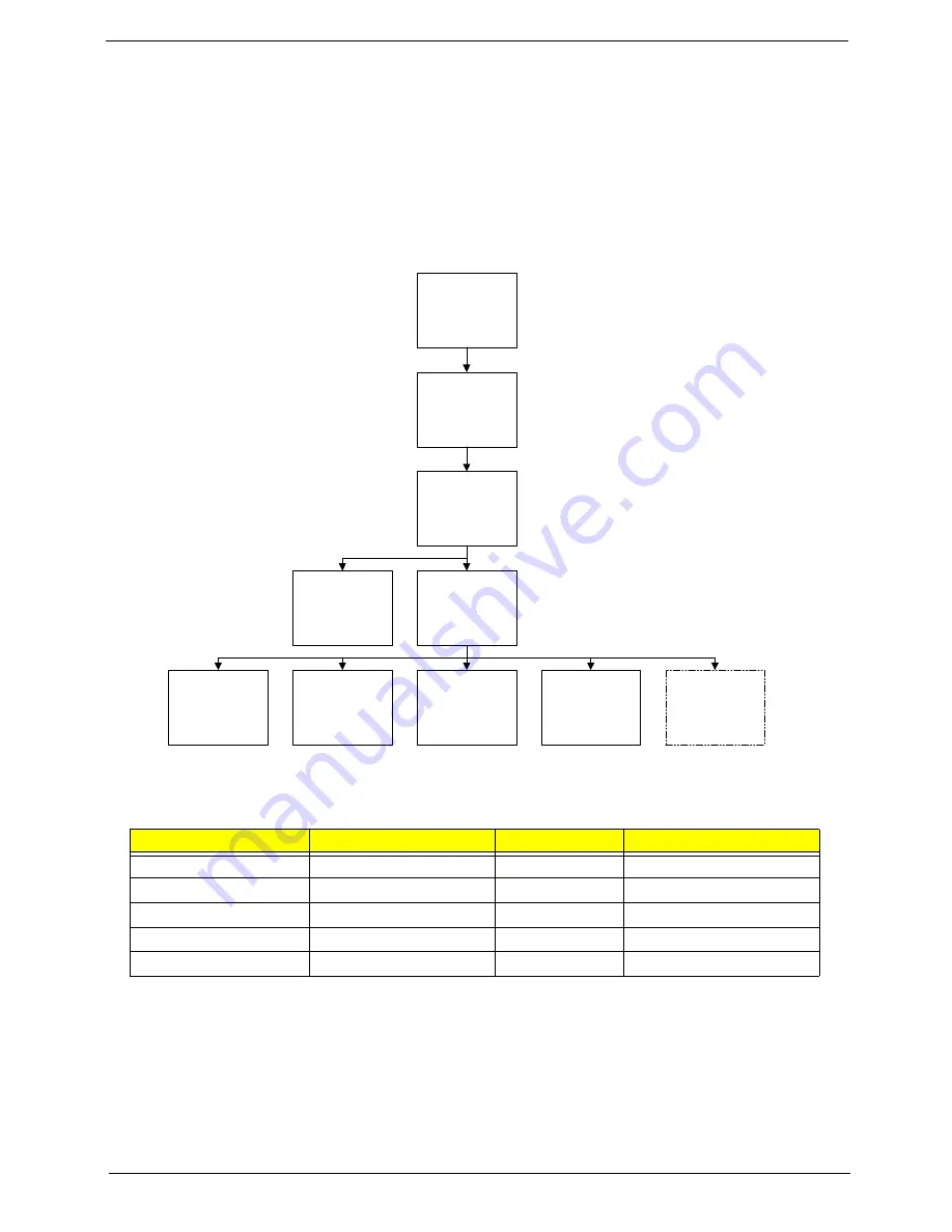
External Modules Disassembly Flowchart

The flowchart below gives you a graphic representation on the entire disassembly sequence and instructs you 
on the components that need to be removed during servicing. For example, if you want to remove the main 
board, you must first remove the keyboard, then disassemble the inside assembly frame in that order.

NOTE: 

Items enclosed with broken lines (— - - —) are optional and may not be present.

Screw List

Step

Screw

Quantity

Part No.

WLAN Module

M2*3

1

86.WBF02.003

ODD Module

M2.5*5

1

86.WBF02.010

ODD Bracket

M2*3

2

86.WBF02.003

Primary HDD Carrier

M3*3

4

86.WBF02.005

Secondary HDD Carrier

M3*3

4

86.WBF02.005

Disconnect power

and signal cables

from system

Remove

Battery

Turn off system
and peripherals

power

Remove

DIMMs

Remove

WLAN

Remove

Primary HDD

Remove

ODD

Remove

Lower Covers

Remove

Dummy Cards

Remove

Secondary HDD

Содержание EasyNote L J Series

Страница 1: ...EasyNote L J Series Disassembly Manual ...

Страница 2: ...ooting Disassembly Requirements To disassemble the computer you need the following tools Wrist grounding strap and conductive mat for preventing electrostatic discharge Flat screwdriver Philips screwdriver Plastic flat screwdriver Plastic tweezers NOTE The screws for the different components vary in size During the disassembly process group the screws with the corresponding components to avoid mis...

Страница 3: ... disassembly process is divided into the following stages External module disassembly Main unit disassembly The flowcharts provided in the succeeding disassembly sections illustrate the entire disassembly sequence Observe the order of the sequence to avoid damage to any of the hardware components For example if you want to remove the mainboard you must first remove the keyboard then disassemble th...

Страница 4: ...t first remove the keyboard then disassemble the inside assembly frame in that order NOTE Items enclosed with broken lines are optional and may not be present Screw List Step Screw Quantity Part No WLAN Module M2 3 1 86 WBF02 003 ODD Module M2 5 5 1 86 WBF02 010 ODD Bracket M2 3 2 86 WBF02 003 Primary HDD Carrier M3 3 4 86 WBF02 005 Secondary HDD Carrier M3 3 4 86 WBF02 005 Disconnect power and si...

Страница 5: ...emoving the Battery Pack 1 Turn computer over Slide the battery lock in the direction shown 2 Slide and hold the battery release latch to the release position 1 then lift out the battery pack from the main unit 2 1 2 ...

Страница 6: ...Chapter 3 47 Removing the SD dummy card 1 Push the SD dummy card all the way in to eject it 2 Pull the card out from the slot ...

Страница 7: ...Lower Covers 1 See Removing the Battery Pack on page 46 2 Loosen the five captive screws in the memory and HDD covers 3 Remove the HDD1 Cover 4 Remove the HDD2 WLAN and Memory Cover as shown HDD1 Cover HDD2 WLAN and Memory Cover ...

Страница 8: ...wer Covers on page 48 2 Remove the screw securing the ODD module 3 Insert a suitable tool into the access slot as shown Gently lever the ODD module out of the chassis 4 Pull the optical drive module out from the chassis Step Size Quantity Screw Type ODD Module M2 5 5 1 ...

Страница 9: ...crews securing the ODD bracket and remove the ODD bracket from the optical disk drive module 6 Remove the ODD bezel by rotating the top edge downward and pulling it clear of the module Step Size Quantity Screw Type ODD Bracket M2 3 2 ...

Страница 10: ...e DIMM Modules 1 See Removing the Lower Covers on page 48 2 Push out the release latches on both sides of the DIMM socket to release the DIMM module 3 Remove the DIMM module 4 Repeat steps for the second DIMM module if present ...

Страница 11: ...Removing the Lower Covers on page 48 2 Remove the adhesive tape securing the Antenna cables in place 3 Disconnect the antenna cables from the WLAN Module NOTE Cable placement is Black to the MAIN terminal left and White to the AUX terminal right ...

Страница 12: ... remove the two screws to release the WLAN Module 5 Detach the WLAN Module from the WLAN socket NOTE When reattaching the antennas ensure the cables are tucked into the chassis to prevent damage Step Size Quantity Screw Type WLAN Module M2 3 1 ...

Страница 13: ...ule in the direction of the arrow to disconnect the interface 3 Lift the HDD Module clear of the HDD bay NOTE To prevent damage to device avoid pressing down on it or placing heavy objects on top of it 4 Remove the four screws two each side securing the hard disk to the carrier Step Size Quantity Screw Type HDD Carrier M3 3 4 ...

Страница 14: ...Chapter 3 55 5 Remove the HDD from the carrier ...

Страница 15: ... be present 1 See Removing the Lower Covers on page 48 2 Using the pull tab slide the HDD Module in the direction of the arrow to disconnect the interface 3 Lift the HDD Module clear of the HDD bay NOTE To prevent damage to device avoid pressing down on it or placing heavy objects on top of it ...

Страница 16: ...Chapter 3 57 4 Remove the four screws two each side securing the hard disk to the carrier 5 Remove the HDD from the carrier Step Size Quantity Screw Type HDD Carrier M3 3 4 ...

Страница 17: ...86 WBF02 003 Modem Board M2 3 2 86 WBF02 003 USB Board M2 5 5 1 86 WBF02 010 Mainboard M2 5 5 1 86 WBF02 010 CPU Fan M2 3 3 86 WBF02 003 Thermal Module M2 5 6 5 4 86 WBF02 009 Remove Mainboard Remove USB Board Remove Switch Cover Remove Keyboard Remove Upper Cover Remove LCD Module Remove LED Board Remove External Modules before proceeding Remove TouchPad Bracket Upper Cover Lower Cover Remove Spe...

Страница 18: ...tery Pack on page 46 2 Lift the Media Board FFC cover as shown to expose the FFC connector 3 Open the FFC locking latch and disconnect the Media Board FFC 4 Remove the three securing screws from the Lower Cover Step Size Quantity Screw Type Switch Cover M2 5 5 3 ...

Страница 19: ...er from the underside of the computer to release the locking latches securing the cover in place 6 Turn the computer over and open the lid fully Lift the left side of the Switch Cover as shown 7 Working along the Switch Cover toward the right hinge gently pry up the cover as shown ...

Страница 20: ...Chapter 3 61 8 Rotate the Switch Cover toward the LCD panel and lift it away from the Upper Cover ...

Страница 21: ...ard 1 See Removing the Switch Cover on page 59 2 Pry the Media Board away from the Switch Cover as shown NOTE A very strong adhesive is used to secure the board in place 3 Pry the board away from the Upper Cover and remove it completely ...

Страница 22: ...See Removing the Switch Cover on page 59 2 Lift the keyboard from the centre as shown to release the securing clips on each side 3 Turn the Keyboard over on the TouchPad to expose the FFC cable 4 Open the locking latch on the FFC as shown ...

Страница 23: ...64 Chapter 3 5 Disconnect the FFC cable from the mainboard 6 Lift the keyboard clear of the chassis ...

Страница 24: ...on page 63 2 Turn the computer over Remove the two securing screws from the bottom of the chassis 3 Open the computer lid and stand the chassis on its edge Ensure the Antenna Cables are free from obstructions as shown Step Size Quantity Screw Type LCD Module M2 5 8 2 ...

Страница 25: ...tape securing the cables in place and pull the Antenna cables through the casing as shown 5 Remove the cables from the cable channel as shown Ensure that the cables are completely free of the retaining clips all the way to the hinge well ...

Страница 26: ...cable from the cable channel as shown Ensure that the cable is completely free of the retaining clips all the way to the hinge well 8 Disconnect the power cable from the Mainboard as shown Ensure that the cable is completely free of the retaining clips all the way to the hinge well ...

Страница 27: ...shown Ensure that the cable is completely free of the retaining clips all the way to the hinge well 10 Remove the four securing screws two each side from the LCD module Step Size Quantity Screw Type LCD Module red callout M2 5 8 2 LCD Module green callout M2 5 5 2 ...

Страница 28: ...Chapter 3 69 11 Carefully remove the LCD module from the chassis ...

Страница 29: ...ee Removing the LCD Module on page 65 2 Turn the computer over Remove the thirteen screws on the bottom panel Step Size Quantity Screw Type Upper Cover red callout M2 5 8 10 Upper Cover green callout M2 5 5 1 Upper Cover blue callout M2 5 3 2 ...

Страница 30: ... Turn the computer over Remove the nine screws on the top panel 4 Remove the adhesive tape holding the cables in place Step Size Quantity Screw Type Upper Cover red callout M2 5 5 8 Upper Cover blue callout M2 5 3 1 ...

Страница 31: ... directly to prevent damage to the connectors Use the pull tabs on FFC cables whenever available to prevent damage 6 Disconnect A as shown 7 Release the locking latch and remove B as shown 8 Release the locking latch and remove C as shown 9 Release the locking latch and remove D as shown A B C D ...

Страница 32: ...he Upper Cover above the Battery Bay lift the Upper Cover away from the Lower Cover as shown 11 Work along the top edge prying the casing apart as shown 12 Pry apart the left and right sides of the casing and lift the Upper Cover away from the Lower Cover ...

Страница 33: ...FC from the cover 3 Remove the single screw securing the TouchPad Bracket to the Upper Cover 4 Hold down the left side of the bracket as shown Lift and pivot the right edge in the direction of the arrow to release the locking latches on the front edge 5 Remove the bracket from the Upper Cover Step Size Quantity Screw Type TouchPad Bracket M2 3 1 ...

Страница 34: ...er Cover on page 70 2 Lift the Media Board FFC as shown to release the adhesive securing it to the Upper Cover 3 Pull the FFC through the Upper Cover as shown Ensure that the cable passes through the casing completely 4 Lift the FFC to remove it from the Upper Cover ...

Страница 35: ...r Cover on page 70 2 Lift the right edge of the LED Board to release the adhesive securing the board to the Upper Cover 3 Lift the LED Board away from the Upper Cover as shown 4 Remove the LED Board from the chassis and slide the FFC through the casing as shown ...

Страница 36: ...0 2 Remove the four screws from the speaker modules 3 Remove the right side Speaker cable from the channel as shown 4 Lift the mylar sheet away from the Upper Cover to expose the Speaker cable Remove the cable from the Upper Cover Step Size Quantity Screw Type Speaker Module M2 3 4 ...

Страница 37: ...78 Chapter 3 5 Lift the entire Speaker assembly clear of the Upper Cover ...

Страница 38: ...Battery IMPORTANT Follow local regulations for disposal of all batteries 1 See Removing the Upper Cover on page 70 2 The RTC Battery is soldered to the Mainboard To replace the battery solder the new battery to the connections shown ...

Страница 39: ... Modem Board 1 See Removing the Upper Cover on page 70 2 Remove the two securing screws from the Modem Board 3 Remove the adhesive tape securing the Modem cable to the Mainboard Step Size Quantity Screw Type Modem Board M2 3 2 ...

Страница 40: ...ft the Modem Board away from the Mainboard taking care not to damage the cable attached to the underside of the board 5 Disconnect the cable from the underside of the Modem Board and lift the board clear of the chassis ...

Страница 41: ... Cover on page 70 2 Disconnect the USB Board cable from the Mainboard connector 3 Lift the USB cable away from Lower Cover to detach the adhesive 4 Remove the single screw securing the USB Board to the Lower Cover Step Size Quantity Screw Type USB Board M2 5 5 1 ...

Страница 42: ...Chapter 3 83 5 Lift the USB Board out of the Lower Cover as shown 6 Remove the USB Board cable from the board connector ...

Страница 43: ...on page 80 2 See Removing the USB Board on page 82 3 Remove the single screw securing the Mainboard to the Lower Cover 4 Lift the Mainboard from the Lower Cover right side first and place it on a clean dust free surface Step Size Quantity Screw Type Mainboard M2 5 5 1 ...

Страница 44: ...page 84 2 Remove the adhesive tape securing the RJ 11 cable to the Lower Cover 3 Remove the RJ 11 cable from the cable channel Ensure that the cable is free from all cable clips 4 Lift the cable bundle away from the Lower Cover to detach the adhesive securing it in place ...

Страница 45: ...86 Chapter 3 5 Lift the RJ 11 Jack away from the Lower Cover to detach the adhesive securing it in place ...

Страница 46: ...n 1 See Removing the Mainboard on page 84 2 Disconnect the CPU Fan power cable from the Mainboard 3 Remove the three securing screws from the CPU Fan 4 Remove the CPU Fan from the Mainboard Step Size Quantity Screw Type CPU Fan M2 3 3 ...

Страница 47: ... Mainboard on page 84 2 Remove the four screws securing the Thermal Module to the Mainboard in reverse numerical order from 4 to 1 3 Using both hands lift the Thermal Module clear of the Mainboard Step Size Quantity Screw Type Thermal Module M2 5 6 5 4 1 2 3 4 ...

Страница 48: ...r 3 89 Removing the CPU 1 See Removing the Thermal Module on page 88 2 Using a flat bladed screw driver rotate the CPU locking screw 180 counter clockwise as shown 3 Lift the CPU clear of the socket as shown ...

Страница 49: ...5 4 86 WBF02 010 M2 4 2 86 WBF02 007 LCD Panel M2 5 5 2 86 WBF02 010 Power Board M2 3 1 86 WBF02 003 LCD Brackets M2 3 6 86 WBF02 003 Remove LCD Panel Remove LCD Bezel Remove LCD FPC Cable Remove LCD Panel from Main Unit before proceeding Remove LCD Brackets Remove Antennas Remove Camera Module Remove Microphone Remove Power Board ...

Страница 50: ...the Hinge Covers 3 Starting from the top centre of the bezel pry the bezel upwards and away from the panel Move along the top edge and down each side until all sides of the bezel are removed NOTE If necessary use a pry to lift up the outside edges of the bezel Step Size Quantity Screw Type LCD Bezel red callout M2 5 5 4 LCD Bezel green callout M2 4 2 ...

Страница 51: ...92 Chapter 3 Removing the Camera Module 1 See Removing the LCD Bezel on page 91 2 Disconnect the camera cable 3 Remove the Camera from the module ...

Страница 52: ...e Camera Module on page 92 2 Remove the two securing screws from the LCD Panel 3 Lift the LCD Panel out of the module rear edge first as shown The LCD Module appears as follows when the LCD Panel is removed Step Size Quantity Screw Type LCD Panel M2 5 5 2 ...

Страница 53: ... LCD Panel on page 93 2 Remove the single screw securing the Power Board Bracket to the LCD Module 3 Lift the Power Board Bracket from the LCD Panel as shown 4 Remove the Power Board from the bracket as shown Step Size Quantity Screw Type Power Board M2 3 1 ...

Страница 54: ...rn the LCD panel over to expose the rear Lift the cable as shown to disengage the adhesive strip securing it in place 3 Remove the adhesive tape and lift the adhesive protector securing the cable to the LCD Panel 4 Disconnect the cable from the panel connector and lift the FPC cable from the panel ...

Страница 55: ...6 Chapter 3 5 Remove the six securing screws three on each side from the LCD Panel brackets 6 Remove the LCD Brackets by pulling away from the LCD Panel Step Size Quantity Screw Type LCD Brackets M2 3 6 ...

Страница 56: ...oving the Microphone Module 1 See Removing the LCD Panel on page 93 2 Remove the strips holding the microphone cable in place Ensure the cable is free from obstructions 3 Lift the Microphone Module clear of the module ...

Страница 57: ...anel on page 93 2 Starting from the right hinge remove the white Antenna cable from the cable channel running along the bottom edge of the LCD Module 3 Remove the adhesive strips holding the left Antenna cable in place Ensure the cable is free from obstructions ...

Страница 58: ...the left side Antenna from the LCD module as shown 5 Remove the adhesive strips holding the right Antenna cable in place Ensure the cable is free from obstructions 6 Remove the adhesive tape green callout and lift the right side Antenna from the LCD module as shown ...

Страница 59: ...s as shown Ensure that the locating pin on each antenna is correctly seated Press down on the adhesive pads green callout to secure the antennas in place 2 Replace the left antenna cable white as shown Ensure that the cable is inserted along the cable channel and secured under each adhesive tab strip Locating Pin Locating Pin ...

Страница 60: ...p 4 Place the Power Board in to the bracket as shown 5 Place the Power Board Bracket in the LCD Module as shown 6 Replace the single screw to secure the bracket in place 7 Place the Microphone Module in the LCD Module as shown and press down to secure it in place 8 Run the cable as shown and secure it using the adhesive tabs ...

Страница 61: ...102 Chapter 3 NOTE The LCD Module appears as shown when the Antennas Power Board and MIC are replaced correctly ...

Страница 62: ...holes on the panel 2 Starting with the top most screws marked with replace the six screws in the brackets as shown 3 Insert the LCD Panel cable into the LCD Panel connector as shown 4 Replace the adhesive strip securing the connector in place 5 Replace the adhesive strip as shown ...

Страница 63: ... panel IMPORTANT Ensure the cable is placed between the green callouts to avoid trapping when the panel is replaced 7 Place the LCD Panel in the back cover bottom edge first and lower it in to place as indicated IMPORTANT Ensure that the LCD cables pass through the hinge wells and are not trapped under the panel ...

Страница 64: ...eplacing the Camera Module 8 Replace the two screws to secure the panel in the LCD Module 1 Align the Camera Board with the locating pins and place the camera in the LCD Module 2 Connect the cable to the Camera Board ...

Страница 65: ...the LCD Bezel 1 Locate the bezel bottom edge first and press down until there are no gaps between the bezel and the LCD Module IMPORTANT Ensure that the LCD cables pass through the hinge wells and are not trapped by the bezel ...

Страница 66: ...wn around the entire perimeter of the bezel until there are no gaps between the bezel and the LCD Module 3 Replace the six screws as indicated NOTE The Bezel securing screws differ in size Red callout M2 5 5 Green callout M2 4 ...

Страница 67: ... The following thermal pads are approved for use Eapus XR PE 1 Place the CPU into the CPU socket as shown taking note of the Pin1 locator 2 Using a flat bladed screw driver rotate the CPU locking screw 180 clockwise to secure the CPU in place 1 Remove all traces of thermal grease from the CPU using a lint free cloth or cotton swab and Isopropyl Alcohol Acetone or other approved cleaning agent 2 Ap...

Страница 68: ...possible to spread the thermal grease evenly 4 Secure the four screws in numerical order from screw 1 to screw 4 in the Thermal Module as shown 1 Align the three screw holes on the CPU Fan and Mainboard and lower the module into place 2 Secure the three screws in the CPU Fan as shown 3 Connect the CPU Fan power cable to the Mainboard connector as shown 1 2 3 4 ...

Страница 69: ... the RJ 11 Jack in the Lower Cover as shown 2 Replace the cable bundle and press down to secure the adhesive in place 3 Run the cable along the Lower Cover as shown using all available cable clips 4 Secure the cable in place with an adhesive strip ...

Страница 70: ...face up the CPU is not visible Place the Mainboard in the chassis left side first 1 then rotate it downward into position 2 2 Ensure that the RJ 11 Modem cable is accessible when the Mainboard is replaced as shown 3 Replace the single securing screw in the mainboard 1 2 ...

Страница 71: ... Board 2 Align the locating holes and pins on the Lower Cover and replace the USB Board 3 Replace the single screw securing the board to the Lower Cover 4 Replace the cable in the cable channel as shown and press down to secure it in place 5 Reconnect the USB cable to the USB Board ...

Страница 72: ...le to the Modem Board 2 Align the screw holes on the Modem and Lower Cover and replace the board 3 Secure the cable in place with adhesive tape 4 Press down as indicated to connect the board to board interface 5 Secure the Modem Board to the Mainboard with two screws ...

Страница 73: ...Speaker cable along the Upper Cover using all available cable clips 3 Continue running the cable along the Upper Cover using all available cable clips 4 Place the right Speaker Module in the chassis as shown ensuring that the locating pins are seated correctly 5 Replace the four securing screws NOTE Ensure that the Speaker cable runs as shown in the image below to avoid trapping when the Upper Cov...

Страница 74: ...ough the Upper Cover as shown 2 Place the LED Board in the Upper Cover and press down as indicated to secure the board in place 1 Place the Media Board FFC on the Upper Cover as shown and press down to secure the adhesive in place 2 Pass the upper end of the cable through the Upper Cover as shown ...

Страница 75: ...ps 1 Rotate the bracket on to the Upper Cover and press down as indicated 2 2 Secure the bracket to the Upper Cover with a single screw 3 Insert the TouchPad FFC in to the connector as shown 4 Close the FFC locking latch to secure the cable in place 1 Place the upper cover on the lower cover front edge first and lower the cover into position 1 2 ...

Страница 76: ...apter 3 117 2 Press down around the front and sides to secure the Upper Cover in place NOTE Ensure that there a no gaps between the Upper and Lower Covers 3 Reconnect the following cables as shown A B C D ...

Страница 77: ... Connect A as shown 5 Insert B as shown and close the locking latch 6 Insert C as shown and close the locking latch 7 Insert D as shown and close the locking latch 8 Secure cables A and B in place using adhesive tape ...

Страница 78: ...er as shown NOTE The securing screws differ in size Red callout M2 5 5 Blue callout M2 5 3 10 Turn the computer over and replace the thirteen screws as shown NOTE The securing screws differ in size Red callout M2 5 8 Green callout M2 5 5 Blue callout M2 5 3 ...

Страница 79: ... four securing screws two each side starting with the left side hinge Ensure that the LCD cables are not trapped in the hinges NOTE The securing screws differ in size Red callout M2 5 8 Green callout M2 5 5 3 Run the MIC cable along the cable channel as shown using all the available cable clips 4 Reconnect the MIC cable to the Mainboard as shown ...

Страница 80: ...e LVDS cable to the Mainboard as shown 7 Run the Power Board cable along the cable channel using all available cable clips 8 Connect the Power Board cable to the Mainboard as shown 9 Run the Antenna cables along the cable channel using all available cable clips 10 Insert the Antenna cables through the chassis as shown ...

Страница 81: ...122 Chapter 3 11 Pull the Antennas completely through from the under side of the computer 12 Secure the cables in place with adhesive tape 13 Replace the two securing screws ...

Страница 82: ...ouchPad area Reconnect the FFC as shown 2 Close the FFC locking latch to secure the cable in place 3 Turn the keyboard over and insert it front edge first into the chassis 4 Press down as indicated to seat the Keyboard NOTE Ensure that the six locating tabs are correctly seated ...

Страница 83: ...124 Chapter 3 Replacing the Media Board 1 Align the Media Board with the transparent pane on the Switch Cover 2 Press the Media Board down to secure it in place with adhesive ...

Страница 84: ...ear edge first on to the Upper Cover Rotate the Switch Cover downward on the Keyboard 2 Press down the edges of the cover to snap it into place then press the centre down until it snaps in to place 3 Turn the computer over and replace the three securing screws as shown ...

Страница 85: ...r 3 4 Lift the Media Board FFC cover as shown to expose the FFC connector 5 Connect the FFC to the Media Board as shown 6 Close the FFC locking latch to secure the FFC in place 7 Replace the Media Board FFC cover ...

Страница 86: ...our screws two each side to secure the carrier 3 Insert the Secondary HDD right side first and lower it into place 4 Slide the Secondary HDD to the right to connect the interface 5 Insert the Primary HDD right side first and lower it into place Slide the Primary HDD to the right to connect the interface ...

Страница 87: ...rew to secure the module 3 Connect the two antenna cables to the module 4 After connecting the cables to the terminals secure the cables in place using adhesive tape NOTE Cable placement is Black to the MAIN terminal left and White to the AUX terminal right 1 Insert the DIMM Module in place 2 Press down to lock the DIMM module in place ...

Страница 88: ... the tray bottom edge first to secure it to the ODD Module 2 Secure the ODD bracket with the two screws 3 Push the ODD Module into the ODD bay until it is flush with the casing 4 Replace the single screw to secure the Module 1 Replace the HDD2 WLAN and Memory Cover back edge first as shown ...

Страница 89: ...as shown IMPORTANT Press down around the perimeter of the covers to ensure that the all the securing tabs are correctly located in the casing 3 Secure the five captive screws to hold the covers in place HDD1 Cover HDD2 WLAN and Memory Cover ...

Страница 90: ...my Card into the slot and push until the card clicks into place and is flush with the casing 1 Slide and hold the battery release latch to the release position 1 insert the battery pack and press down 2 2 Slide the battery lock in the direction shown to secure the battery in place 1 2 ...

Страница 91: ...132 Chapter 3 ...

Отзывы: