7
B. Changing the Drive Belt Continued.
4.
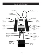
Turn the 2 tension rods counter clockwise equal
turns until you can push the bearing hub plate to the
rear (3/4-inch socket).
5.
Remove the old belt and install the new one.
6.
Tension the new belt by reversing step #4. The
belt should be just tight enough to not slip or squeal.
Care must be taken not to over tension the belt. Over
tension will cause premature bearing wear.
7.
Retighten the 4 bearing hub plate mounting bolts.
8.
Replace the front cover.
C. CHANGING THE ANGLE OF ATTACK (PAD TO
FLOOR) & THE HEAD PRESSURE.
If the machine has been dropped or you notice a dis-
tinct increase in the torque during operation, this ad-
justment may be needed. For this operation, you will
need: a ¾-inch wrench, a new pad installed on the
machine, a framing level, a wood block and shims,
and a level floor
area on which to set the machine. The end results of
this operation should be a machine with framework
that sets slightly low in both the rear and on the right
side. The right frame should be 1/8-inch lower than
the left frame at the wheel bracket point. You may
measure the distance from the top of the axle plate to
the top of the main frame to establish this difference.
Th 1/8-inch variance from the left to the right is criti-
cal for level buffing and ease of operation. If the dif-
ference is increased (more than 1/8- inch), torque re-
lief will increase but level buffing will decrease; you
will shine harder on the right side of the machine than
the left. If the difference is decreased (less than 1/8-
inch), torque relief will decrease and level buffing will
increase. The machine will be harder to operate. When
you get it right, the machine will deliver good level
buffing with a minimum of operating effort.
1.
Install a new pad onto the machine.
2.
Place the machine onto a level floor area.
3.
Remove the LP tank.
4.
Place the wood block and shims under the tails of
the right and left main frames of the machine; enough
to slightly raise the wheels from the floor.
5.
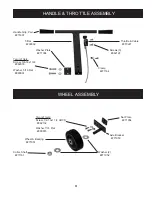
Loosen the right and left axle brackets, two bolts
each.
6.
Level the left main frame with the framing level.
You will need to remove the wood shims as this is
done. Tap the wheel up or down as needed to main-
tain floor contact. The frame should be slightly low in
the rear (about ¼ inch below level at the tail).
7.
When this measure is achieved, tap the left wheel
to the floor and tighten the mounting bolts.
8.
Now measure the distance between the top of the
left wheel bracket and the top of the left main frame.
9.
Subtract 1/8-inch from the measurement in step
#8. Set the right wheel bracket to this new mea-
surement.
10.
Tighten all wheel bracket mounting bolts and re-
move the wood block and shims.
If the unit seems to over torque after a test run,
you
may correct this problem by simply raising both wheel
brackets equal amounts. This adjustment changes the
angle of attack pad to floor and should be made in
small 1/8-inch increments. Always keep the right
frame 1/8-inch lower than the left at the wheel bracket
point.
If you desire to increase the head pressure of your
unit,
simply move the right and left axle brackets to
the rear equal amounts. Make this move in ½ inch
increments. Test run the unit after each adjustment
until you reach the desired head pressure. If you find
that you have increased the head pressure and increased
the torque, the torque may be decreased by raising both
the right and left wheels equal amounts. The wheel
system on this unit is designed for the professional.
There are enough adjustments to make the machine
buff any way you want. The ability to control the head
pressure and angle of attack ate advantageous to level
buffing, ease of operation, and superior pad life.
Содержание NIGHTHAWK 20
Страница 4: ...NOTES 4 ...
Страница 15: ...15 NOTES ...


