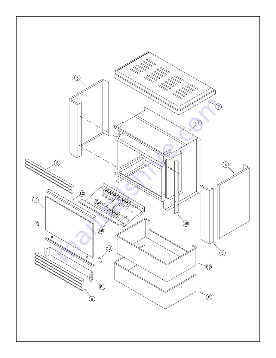
10
Fig. # 14
f i r e - p a r t s . c o m
Страница 1: ...asoline or other flammable vapors and liquids in the vicinity of this or any other appliance WHAT TO DO IF YOU SMELL GAS Do not try to light any appliance Do not touch any electrical switch do not use any phone in your building Immediately call your gas supplier from a neighbour s phone Follow the gas supplier s instructions If you cannot reach your gas supplier call the fire department Installati...
Страница 2: ...TENANCE 3 LIGHTING INSTRUCTIONS 4 OPERATING 5 BURNER 5 CONTROL 5 GAS FLAME ADJUSTMENT 5 GAS SUPPLY 6 ELECTRICAL 6 BLOWER OPERATION 6 CLEARANCES 6 INSTALLATION AND VENTING 7 FLOOR PROTECTION 7 LOG SET 8 REPLACEMENT PARTS 9 fire parts com ...
Страница 3: ...e appli ance be kept clean It is Pacific Energy s policy that no responsibility is assumed by the Company or by any of its employees or representatives for any damages caused by an inoperable inadequate or unsafe condition which is the result either directly or indirectly of any improper operationorinstallationprocedures MAINTENANCE Caution Turn off gas and electrical power supply and allow ample ...
Страница 4: ...y electric switch do not use any phone in your building Immediately call your gas supplier from a neighbour s phone Follow the gas supplier s instructions If you cannot reach your gas supplier call the fire department C Use only your hand to push in or turn the gas control knob Never use tools If the knob will not push in or turn by hand don t try to repair it call a qualified service technician F...
Страница 5: ...ufacturing process This condition is temporary Open doors and windows to ventilate area GAS FLAME ADJUSTMENT The air shutter on the burner venturi tube controls the primary combustion air to the gas burner Although it is preset at the factory some adjustment may be necessary to obtain desired flame and to eliminate carbon deposits See Fig 4 for proper flame pattern Naturalgas 3 16 open Propanegas ...
Страница 6: ... remove burner assembly 1 Lift glass up by the bottom tabs until it clears the bottom shelf andremove 2 Remove all logs from firebox taking care not to damage them 3 Remove 2 screws located in the front bottom holding burner in place see Fig 6 4 Lift burner up on the left side just enough to slide whole assembly to the left to disconnect from the orifice 5 Remove burner through front opening To re...
Страница 7: ...ng with the vent safety shutoff system can result in carbon monoxide CO poisoningandpossibledeath Note This appliance has a draft hood built in and when installed according to these instructions the draft hood is in the same atmospheric pressure zone as the combustion air inlet to the appliance Adequate combustion and ventilation air must be provided for safe and proper operation The Mirage Gas Ap...
Страница 8: ...cing rear and the bark side forward The tabs should fit into notches of log 2 Place the large middle log on centre tabs of burner assembly Locate log on top of tabs with flat part down hollow part facing rear and bark side facing forward 3 Front log locates on channel in front of burner Flat part down and curve up on the left side 4 The top Y log bridges across from the front log to the large cent...
Страница 9: ... FITTING 38 INLET PIPE 39 BURNER SUPPLY TUBE 40 ORFICE CONNECTOR FITTING 41 ORIFICE NAT GAS 42 ORIFICE LP 43 VENTURI TUBE 44 VENTURI GASKET 45 BURNERASSEMBLY 46 PILOT ASSEMBLY NAT GAS 47 PILOT ASSEMBLY LP 48 PILOT ORIFICE NAT GAS 49 PILOT ORIFICE LP 50 THERMOPILE 51 PILOT SUPPLY TUBE 52 BUSHING 53 WIRE STRAIN RELIEF 54 WIRE NUT 55 CONTROL BRACKET 56 ORIFICE HOLDER 57 1 4 SPACER 58 CONTROL PANEL BR...
Страница 10: ...10 Fig 14 fire parts com ...
Страница 11: ...11 Fig 15 fire parts com ...
Страница 12: ...12 Printed in Canada Pacific Energy Gas Stoves Box 29 1394 Fisher Road Cobble Hill B C V0R 1L0 fire parts com ...