background image

13

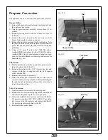
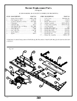
Fig. #24

Fig. #23

Fig. #22

Louver Installation

Unpack and inspect all parts. A flathead or a #2 Robertson
screwdriver is required to install the louvers.

1) Fasten top louver to the top casing with the screws

provided (see Fig. #22).

2) Fasten bottom louver to the hinge brackets at the bottom

of the appliance (see Fig. #23).

Optional Radiant Overlay

The optional Radiant Overlay may be installed at any time.
Unpack and inspect all parts. Install Overlay as follows:

1) Remove the glass frame as outlined in "Glass Frame
Removal" section. Place face up on a flat, stable surface to
avoid damage.

2) Remove screws retaining front trim and set trim aside.

3) Position Radiant Overlay over top of frame.

4) Replace trim and screws (Fig. #24).

5) Reinstall complete assembly onto appliance. During in-
stallation ensure that the tabs on the top of the unit engage the
corresponding slots in the glass frame.

Содержание Brentwood Gas Insert

Страница 1: ...not touch any electrical switch do not use any phone in your building Immediately call your gas supplier from a neighbour s phone Follow the gas supplier s instructions If you cannot reach your gas su...

Страница 2: ...8 Surround Assembly 9 Log Set 10 Glowing Embers 12 Levelling Legs 12 Glass Frame Installation 12 Louver Installation 13 Optional Radiant Overlay 13 Lighting Instructions 14 First Fire 15 Operation 15...

Страница 3: ...e your Pacific Energy Brentwood Gas Insert without first reading and understanding this manual Any installation or opera tional deviation from the following instructions voids the Pacific Energy Gas S...

Страница 4: ...any gas control which has been under water Glass Panel Warning Do not operate appliance with glass panel re moved cracked or broken Replacement of the glass panel should be done by a licensed or qual...

Страница 5: ...nstallation code in Canada or the National Fuel Gas Code ANSI Z223 1 1988 in the USA and approved per local codes Only qualified licensed or trained personnel should install this product Only listed t...

Страница 6: ...o combustible surfaces are shown on Fig 5 and 6 Adequate clearances aroundairopeningsandcombustionairsuppliesarerequired Fig 6 Fig 5 Minimum Clearances to Combustibles installed as a fireplace insert...

Страница 7: ...ply Caution The gas line should be installed by a qualified service person in accordance with all building codes Consult local and or national building codes before pro ceeding The gas valve inlet acc...

Страница 8: ...nce 4 Position the spill switch over the two holes and fasten in place with the two screws Fig 9 5 Install surround assembly Connect remaining wire leads to the rocker switch on the surround trim Draf...

Страница 9: ...at the joint 3 Assemble the three trim pieces using the enclosed hard ware Slide Part F into the back corners of the trim and tighten screws Ensure the mitred corners fit tightly and evenly Fig 13 4...

Страница 10: ...connections should be made before installing logs All logs are numbered on the underside for their order of assembly Position the logs as indicated by pictures below Notches on the underside of logs 2...

Страница 11: ...11 Step 7 Rear Right Log Placement log 7 Step 6 Rear Left Log Placement log 6 2 7 5 3 6 4 Fig 17f 1 Step 5 Top Right Log Placement log 5 Fig 17e Fig 17d...

Страница 12: ...rner and fan cover may be removed to access the weld nuts from inside Fig 18 The legs thread into the nuts and protrude out the bottom raising the rear of the appliance until it is level with the fron...

Страница 13: ...y The optional Radiant Overlay may be installed at any time Unpack and inspect all parts Install Overlay as follows 1 Remove the glass frame as outlined in Glass Frame Removal section Place face up on...

Страница 14: ...and call your service technician or gas supplier 9 Turn gas control knob counter clockwise to On position 10 Turn HI LO burner control knob to desired setting 11 Close bottom grill and turn on the bur...

Страница 15: ...valve behind the bottom louver as shown in Fig 26 Pulling the rod forward closes the shutter and increases the flame Manual HI LO Flame Adjustment Fig 25 The HI LO burner control knob can be rotated i...

Страница 16: ...ft up and forward to disengage from the top frame tabs Placetheglassframeassemblyinasafeplaceto avoid damage 3 Notelogspositionandcarefullyremove taking care not to damage them 4 Remove glowing embers...

Страница 17: ...nt com pound to the orifice threads to ensure a good seal into the manifold Fig 31 Pilot Orifice 1 Pull the pilot hood assembly up and off to gain access to the pilot orifice Fig 32 33 2 Remove the or...

Страница 18: ...Electrical Code and in the USA with the National Electrical Code ANSI NFPA 70 latest edition Installation The burner assembly must be removed for blower kit installation Follow BurnerRemoval sectionf...

Страница 19: ...replaced Fig 37 6 Slide 1 2 grommet with wires into the key hole provided on the fan cover Fig 38 Note Ensure that wires are not touching the bottom of the burner as damage could occur 7 Replace fan...

Страница 20: ...ard size MINC 1658_ _ Surround Side Left met black std size MINC 16581MB Surround Side Left embossed BWGA 16582_ _ Surround Side Left over size MINC 1661_ _ Surround Side Left met black over size MINC...

Страница 21: ...21 Fig 40 11 14 20 5 13 9 17 2 5 4 19 1 16 15 8 6 10 7 12 5 18 3 14...

Страница 22: ...iter 5016 5 7 Valve Cover MIND 186201 8 Manifold 5012 51 9 Burner Orifice 3 32 5021 31 10 Andiron Assembly BRNA 198531 11 Venturi Tube Assembly BRNA 501131 12 Air Shutter Rod 1752 13 Venturi Tube Gask...

Страница 23: ...codes locaux S il n existe aucun code local se conformer a la norme CAN CGA B149 en vigueur Left and Right side are determined when facing the front of the appliance Les cotes droit et gauche se dete...

Страница 24: ...Printed in Canada Pacific Energy Fireplace Products Ltd Box 1060 Duncan BC V9L 3Y2 Phone 250 748 1184 Web site http www pacificenergy net...

Отзывы: