PAC 750XL
22
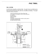
Fuel is drawn from a 26 litre (6.8 U.S. gallon sump tank incorporated into the left forward tank.
During normal operations fuel is drawn from the tanks by a pump driven by the engine. During
starting and emergency operation an electric auxiliary pump mounted in the sump tank provides
fuel motive force. The quantity of fuel pumped is in excess of that required for engine operation.
Fuel not required by the engine is circulated to each tank where it passes through “jet pumps”
which uplift more fuel by venturi-action. Fuel from each rear tank is fed forward to its
corresponding side front tank where “jet pumps” draw fuel and deliver to the sump tank.
Operation of the fuel system is monitored by three warning systems. A red warning light
marked in the annunciator lights panel which will illuminate should the system pressure fall to 2
psi + 10% psi. An amber warning light in the annunicator panel will illuminate should the
pressure differential across the inlet and outlet ports of the fuel filter rise above 2.5 psi + 0.20
psi. A low fuel quantity light is also fitted. The system is vented by two pipes which connect
front and rear tanks respectively before venting overboard through the fuselage lower surface
under the cabin.
The contents of each wing tank is measured by a capacitance sensor and indicated on dual
digital indicators in the instrument panel.
The wing fuel storage tanks comprise front and rear cells fabricated in the centre wing structure
on the left and right hand sides of the fuselage. Each front tank is equipped on the upper
surface with a filler aperture and cap and a quantity sensor, in the lower surface access panels,
and drain points. Each rear tank is equipped on the upper surface with three access panels one
of which incorporates the filler aperture and cap, in the lower surface are two drain points. A
quantity sensor is mounted diagonally across the tank.
The fuel shut-off valve is located under the floor of the cockpit on the fuselage left side between
the sump tank and the fuel filter. It is operated from a simple ON/OFF push/pull lever mounted
on the control centre console.
ELECTRICAL SYSTEM
The electrical system is a 28 V DC single wire negative earth return system. Power is provided
from two internal sources. The generator system, as a main source under normal conditions,
and the battery system which is employed for engine starting and system operation when
generator power is not available (engine not running or generator is off line). Both systems feed
a common bus bar. Control and monitoring of power from the two systems is by a MASTER
switch, voltmeter and ammeter respectively. All circuits are protected by circuit breakers or
fuses. Wiring is installed in open looms supported by clips and protected with sleeving where
necessary. Wiring routed to the forward part of the engine compartment passes through
stainless steel ducts to protect it from heat. Disconnect points are provided for the removal of
all major components.
The battery system comprises a 24 V 43 amphere battery, a master relay and associated wiring.
The system supplies power for engine start and operation of the electrical system when the
generator is not running or has failed. The battery is isolated from the bus bar by the master
relay (de-energised).
The generator system comprises a starter generator, a Generator Control Unit (GCU), a relay, a
GCU control switch marked GENERATOR, a circuit breaker, a generator warning light,
associated wiring and terminal blocks. The GCU provides output voltage control, system over
voltage protection and reverse current protection for the generator.


