


BOSS 4.5, RF, P3 & P4 OWNERS MANUAL 21
Disassembly and Assembly
Last you need to remove the Footplate/Stabilizer wheel assembly from the front of the wheelchair, by
removing the two winged bolts or pull pin holding it to the main frame assembly. Raise the front footplate
section up out of the way.
REASSEMBLING THE WHEELCHAIR
To reassemble the wheelchair, simply repeat the same steps in reverse order. 1.) Replace the foot plate on the
frame assembly and replace the winged bolts.
WARNING never operate the unit without reattaching the front section and the bolts/wing-nuts or pull
pin which holds the front section in place!
Put the batteries in place and connect the battery cables. Align the red dots on each connector so that they
line up. Push the plug straight in until the connectors click together. Place the connectors between the
batteries.
Replace the rear cover by running the control cable through the hole in the cover and setting the cover securely on
the frame. Make sure the velcro on the cover attaches to the velcro on the rear frame support piece.
Place the seat assembly onto the four height adjustment posts. Connect the control cable to the controller.
Follow the entry instructions elsewhere in this manual, and go for a ride.
INFINITELY ADJUSTABLE ANTI-TIP WHEELS
The anti-tip wheels are normally positioned approximately 1/2” off the fl oor for indoor use (with a rider in
the chair) but may be adjusted in height. Because Scout Explorer is a “midi” (3/4) drive chair the anti-tip
wheels are normally only used when braking going forward down a steep incline. The lower setting causes
the powerchair to tilt forward at a lesser angle before resting on the anti-tip wheels if you decelerate rapidly
while going down a hill. See specifi cation page for maximum obstacle climbing capability. Always keep
anti-tip wheels at the same height from fl oor to prevent possible tipping to the side.
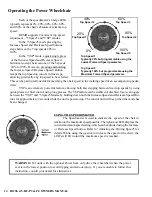
ANTI-TIP ASSEMBLY STANDARD SETTINGS
- To RAISE the wheel height, turn the thumb screw clockwise until the wheels are in the desired position.
- To LOWER the wheel height, turn the thumb screw counter-clockwise until the wheels are in the desired
position.
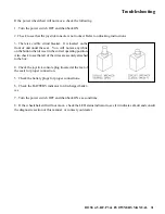
FINGER ADJUSTABLE FRONT ANTI-TIP ASSEMBLY
- Wheels set lower will provide additional stability
- Wheels set higher will provide additional clearance
over obstacles


