5
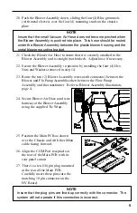
20. Push the Blower Assembly down, sliding the four (4) Blue grommets
(with metal sleeves) over the four (4) mounting studs on the chassis
plate.
NOTE
Insure that the small Vacuum Air Hose does not become pinched when
the Blower Assembly is pushed into place. This hose should be routed
under the Blower Assembly between the plastic blower housing and the
metal blower mounting bracket.
21. Check the Blower Air Hose to insure that it is securely attached to the
Blower Assembly and is straight (not kinked). Adjust hose if necessary.
22. Secure the Blower Assembly in position by installing the four (4) Hex
Nuts and Washers removed in step 14.
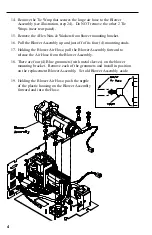
23. Route the two (2) Blower Assembly wires (with connector) between the
Blower and Flo Pump Assemblies then between the Flow Pump
Assembly and the transformer. Refer to Blower Assembly illustration,
page 4.
NOTE
Insure that the plug pins are lined up correctly with the connector. The
system will not operate if this connection is incorrect.
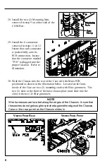
24. Secure Blower Air Hose (and wire
harness) at the Blower Assembly
using the supplied Tie Wrap.
25. Position the Main PCB as shown
over the Chassis and with the ribbon
cable facing forward.
26. Align the COM Port receptacle at
the rear of the Main PCB with its
rear panel cutout
27. There is a ten (10) pin plug mounted
at the rear of the Main PCB.
Carefully insert these pins into the
matching 10 pin connector on the
HV Board.


