background image

7

www.p-light.com

established 2000

Elektronics

Batteri-/Energy monitor

Terminals 5, 7, 9 and 10 have battery monitors to prevent deep 

discharge which will damage the batteries (also frost protection). 

Terminal 10 is switched off at 19 V and others at 21 V. All terminals 

open  again  when  charging commences and  the voltage exceeds 

23.5 V.
Terminal 10 also has an energy monitor = If P-LIGHT is inactive for 

270 hours, terminal 10 is closed and opens again when the parking 

lights come on again via P-LIGHT (pushbutton 1) or the truck. 

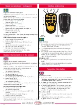
Built-in test program

P-LIGHT® comes equipped with its own test program for monitoring 

and fault tracing. In order for the test program to show all values, 

the truck’s lighting must be switched on.
To access the menu, press and hold pushbutton 1 on the P-LIGHT® 

box for approx. 8-10 seconds. You can release the button when the 

program starts. A rolling menu is then shown on the controller’s 

display. The program’s version number is displayed first, followed 

by the voltage (V), in the following order.
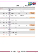
Code Terminal 

Benchmark

U4 Voltage on terminal 4 (Circuit 1 in) 


min 24V

U6 Voltage on terminal 6 (Circuit 2 in) 


min 24V

U8 Voltage on terminal 8   


0V

UC Voltage out from the

built-in charger/booster                     

approx. 28V/20°C

U1 Voltage on terminal 1   

approx. 25V

(P-LIGHT® batteries)
A tripped MCB is indicated by the text “Err” alternating with “f x” 

where “x” is the MCB that has tripped.

Error code on P-LIGHT, C11 och CC1

If the error code “C11” or “CC1” appears on the display, it means 

that the batteries have been deeply discharged with low battery 

voltage as a result. This may be due to both a fault in the charger, 

but also a large output demand without the battery having had 

time to recharge sufficiently while driving the vehicle.
If the battery voltage drops below the programmed limit, terminal 

10  (AUX)  switches  off  and  then  indicates  “C11”  on  the  display. 

Restarting  requires  5  minutes  of  voltage  on  terminals  4  and  6 

(truck connected and lighting on). If the voltage in the batteries 

after this time exceeds the programmed limit, terminal 10 (AUX) 

is activated again. It is important that the batteries have time to 

receive a proper charge again after this.
If the voltage does not exceed 24 V after 5 minutes, terminal 10 

(AUX) remains off and “CC1” appears instead. This test is repeated 

each time voltage is connected to terminals 4 and 6 for at least 5 

minutes. If the “CC1” indication does not clear after a few attempts, 

the charger or batteries are probably damaged. In this case, contact 

the appropriate workshop for inspection and possible replacement 

of the controller/batteries.

Programmable switching

Press and hold pushbutton 2 (the top one) for at least 20 seconds.
A message will then appear on the display, do you want to change, 

repeat the procedure.
AUT ON = P-LIGHT® ALWAYS switches on outputs 5 and 7 when the 

truck is switched off or disconnected.
AUT OFF = P-LIGHT® NEVER switches on outputs 5 and 7 when the 

truck is switched off or disconnected (Factory setting on delivery).

Resettable circuit breaker funktion

If  any  of  the  MCBs  trip,  this  is  shown  on  the  display  (on  the 

controller)  by  an  alternating  message  of  “Err”  and  “F  x”,  where 

“x” is the tripped MCB-ID. If the truck is disconnected, the circuit 

breaker fault is only displayed for 30 seconds after pressing the 

button, to save the battery. However, if the vehicle is connected, 

the message is displayed continuously.
NOTE: If a MCB trips, the supply must be disconnected (for 15-60 

sec) in order for the MCB to reset. If the tripped circuit breaker has 

been caused by a short-circuit in a bulb, this must also be rectified.

Terminals 5, 7, 9 and 10 have built-in MCBs, max simultaneous 

output 270 W (11 A).
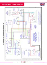
If,  for  some  reason  it  is  necessary  to  bypass  the  P-LIGHT® 

controller, the wires on terminals “4” and “5”, as well as “6” and 

“7”, must be connected together.

Fuse id

Func�on

1

Terminal 1 (Ba�ery)

5

Terminal (Out cct 1)

7

Terminal 7 (Out cct 2)

9

Terminal 9 (Out Op�on)

10

Terminal 10 (Out AUX)

C

Charger

Содержание Maxi XL Magnum HydroComp

Страница 1: ...ng diagrams 18 19 Radio 20 23 Drawings 24 26 Replacement of batteries Magnum Frame 27 F r anv ndare For users F r Benutzer K ytt jille 28 29 Service Wartung Huolto and Own note 30 Trailer connectors i...

Страница 2: ...styrenhet f rbrukar en mindre vilostr m 3mA vilket g r att batterierna ska vara fullt uppladdade innan l ngre avst llning av sl pet trailern sker Vid mer n 1 m nads avst llning ska kabels kringen vid...

Страница 3: ...terstart kr vs 5 minuters sp nning p plint 4 och 6 lastbilen tillkopplad och belysning p Om sp nningen i batterierna efter denna tid verstiger programmerad gr ns aktiveras plint 10 AUX igen Viktigt a...

Страница 4: ...kering 30 Ut 24V Vippstr mbrytare Se kopplingsschema fabrikskopplad fr n plint 31 31 Ut 24V till togglande vippstr mbrytare f r extern radiostyrning fabrikskopplad fr n plint 10 AUX 32 Vippstr mbrytar...

Страница 5: ...i bruk Obs Gnista kan uppkomma d styrenheten startar och laddas upp 5 www p light com established 2000 Inkoppling Maxi XL Inkoppling Magnum Frame F r inkoppling av P LIGHT HydroComp se separat kopplin...

Страница 6: ...be fully charged before the trailer taken out of service for any length of time If it is to be taken out of service for more than 1 month the cable fuse at the batteries must be removed Warranty and...

Страница 7: ...ting requires 5 minutes of voltage on terminals 4 and 6 truck connected and lighting on If the voltage in the batteries after this time exceeds the programmed limit terminal 10 AUX is activated again...

Страница 8: ...nd 7 26 Output 24 V to pushbutton 1 Parking 30 Output 24 V Toggle switch See wiring diagram factory connected from terminal 31 31 Output 24 V to toggle switch for external radio control factory connec...

Страница 9: ...31 och 32 Max 200W 34 Gnd PTO 41 Power output PTO Solenoid max 100A C O N T A C T T R A I L E R Outgoing ligh ng circuit 1 Outgoing ligh ng circuit 2 Magnum 58 R 58 L Clutch box on trailer Outgoing l...

Страница 10: ...f r einen l ngeren Zeitraum abgestellt wird Betr gt die Abstelldauer mehr als 1 Monat muss die Kabelsicherung an den Batterien entfernt werden Gew hrleistung und Funktion F r P LIGHT bieten wir eine...

Страница 11: ...C11 angezeigt F r den Neustart ist eine 5 min tige Spannung an Klemme 4 und 6 erforderlich Lkw angeschlossen und Beleuchtung eingeschaltet WenndieSpannungindenBatteriennachdieserZeit die programmiert...

Страница 12: ...Wippschalter Siehe Schaltplan werkseitig von Klemme 31 angeschlossen 31 24 V Ausgang an Tastschalter f r externe Fernbedienung werkseitig von Klemme 10 angeschlossen AUX 32 24 V Ausgang an Wippschalte...

Страница 13: ...gleichzei ge Leistungsaufnahme 270 W 11 A Nebenantrieb PTO Solenoid max 100A Anschlusskasten am Anh nger Steuerger t 1 10 A Beleuchtungs kreis lauf 1 Beleuchtung kreis lauf 2 Magnum 58 R 58 L Anschlu...

Страница 14: ...aa 3mA joten akkujen tulee pidemm n seisokin ajan olla t yteen ladattuja Yli 1kk seisokin ajaksi tulee akkujen lataussulake poistaa Takuu ja toiminta P LIGHT my nt 1 vuoden tuotetakuun Takuua sioissa...

Страница 15: ...0 AUX sammuu ja n yt lle tulee ilmoitus C11 Uudelleenk ynnistys vaatii j nnitteen nastalle 4 ja 6 viiden minuutin ajaksi auto kytkettyn ja valot sytytettyin Jos akkujen j nnite t m n j lkeen ylitt ase...

Страница 16: ...Katso kytkent kaavio tehdaskytketty liittimelt 31 31 Out 24V vipukytkimelle ulkoista radio ohjainta varten tehdaskytketty liittimelt 10 AUX 32 Out 24V jousipalautteiselle vipukytkimelle Katso kytkent...

Страница 17: ...kuormitus 5 Max 100W 7 Max 100W 9 Max 200W 30 31 ja 32 max 200W 34 Gnd PTO 41 Voiman uloso o Solenoidi max 300A Magnum 58 R 58 L 58 R 58 L 6 4 7 5 3 3 Akun kapasitee Ah 120 150 200Ah J nnite V 24V La...

Страница 18: ...www p light com established 2000 18 Wiring diagram Maxi XL and Magnum Maxi XL Magnum...

Страница 19: ...19 www p light com established 2000 Wiring diagram HydroComp 1 axle steering HydroComp 1 axle steering...

Страница 20: ...Ex Luftfj rding Ner Air suspension Down Ex Dragst ng Ner Drawbar Down Ex Axellyft 2 Axle lift 2 Ex Blixtljus fram Strobe Lights Front Ex Arbetsbelysning Work Lights Revers light to no 8 and strobe li...

Страница 21: ...s 1 5 NC 6 IN Of r ndrad 5 Black 1 7 NO 32A Pink Togg On Off Off Unchanged 8 NC 9 IN 2 Black 2 10 NO 30B Brown Mom Yes 1 11 NC 12 IN Of r ndrad B Red 3 13 NO Togg On Off Off Unchanged 14 NC 15 IN 3 C...

Страница 22: ...button Keep pressed at least 4 seconds All relay LEDs light red All relay LEDs go out 3 Release the receiver Select button All transmitters are erased from the receiver If the function LED flashes re...

Страница 23: ...emot ett radiopaket fr n en annan s ndare n en Panther Receiving a radio packet from a transmitter other than a Panther 8 12 9 11 Yellow Green x x Tar emot ett radiopaket fr n en s ndare inst lld p e...

Страница 24: ...g and dimensions HydroComp 1 axle steering HydroComp Drawing 24 295 630 587 326 Electrical connections Steering Left Steering Right Steering Left Steering Right Exhaust Rear axle Pressure Exhaust Rear...

Страница 25: ...lished 2000 590 560 276 5 261 Electrical connections Pushbutton Options Switch Mom 30 Switch Mom 32 Switch Extra 3 Pushbutton Parklight Main breaker Switch AUX Terminal 10 Drawing and dimensions Maxi...

Страница 26: ...ame Drawing Magnum Frame 435 493 Magnum Frame 567 626 306 690 Swith AUX Terminal 10 Pushbutton Parklight Pushbutton Options Main breaker Switch Mom 30 Electrical connections Switch Mom 32 Switch Extra...

Страница 27: ...electronics front without damaging the cables Nu blir ba erierna l tkomliga lossa ba erikablarna och ba erif stena och byt ba erier Now the ba eries become easily accessible disconnect the ba ery cab...

Страница 28: ...rivning 1 When the vehicle moves forward WITHOUT auxiliary steering A BELOW set EBS speed Inactive position Normal Pneumatic locking valve s are active and open hydraulic locking valve is open NO i e...

Страница 29: ...en ein Hydrauliksteuerung f r 1 2 Nachlaufachsen mit pneumatischer Achssperre 1 davon mit Zusatzlenkung F r einen Test der Steuerung muss die Klemme V MAX 24 V vom EBS System beziehen HINWEIS Lesen Si...

Страница 30: ...da innan fordonen tas i bruk InnoNet AB har endast levererat komponenter och rekommenderade inkopplingar funktioner och ansvarar inte f r eventuella skador som kan uppkomma vid montering eller anv ndn...

Страница 31: ...Li axle Ground Gnd 3 CAN H ej f r EBS eller ABS CAN L ej f r EBS eller ABS 1 Ground GND for pin 1 3 and 5 12 2 Indica on of applied parking brake due to loss of air pressure 3 Ground GND f r pin 14 an...

Страница 32: ...ww p light com www innonet se P LIGHT Control unit Manufactory No Trailer Company City Country Sign Manufactory date Fill in and attach with the vehicle trailer that P LIGHT is mounted on Electric box...

Отзывы: