CDV Construction Manual – Issue 3
Page 21
CAL Freq
The accuracy of the VFO frequency is dependent on a number of factors. These include practical
limitations in the clock generator fractional dividers, the necessary rounding of calculations in
firmware and the tolerance of the crystal clock frequency. The result is that the actual VFO
frequency may not match the displayed frequency. This option allows trimming of the VFO
output frequency in firmware so that the operating frequency matches the displayed frequency.
CAL Volts
The microcontroller measures the battery voltage using an analog to digital converter through a
resistive divider. Due to the tolerance in the resistors and voltage reference within the
microcontroller the displayed voltage may not be exact. This option allows the displayed value
to be trimmed to match the correct value.
SIDEBAND
The CDV displays
USB
or
LSB
and calculates output frequencies depending on the state of the
U/L input wire. This option allows the state to be reversed.
If the IF Offset option is set to NONE, the USB/LSB state will be ignored.
LO V Alarm
This option flashes a low voltage message on the OLED when the supply voltage goes below the
programmed limit. This is helpful when operating on batteries to avoid excessive discharge.
9.4
M
ENU
O
PTION
R
ANGES
Menu
Option Ranges
Fixed O/P
NO
YES
BFO
Fixed Freq
100KHz to 100MHz in 1Hz steps
OFFSET
VFO > IF
VFO < IF
NONE
IF HI Freq
100KHz to 100MHz in 1Hz steps
IF LO Freq
100KHz to 100MHz in 1Hz steps
TX Freq
100KHz to 100MHz in 1Hz steps
STEPS
1Hz, 10Hz, 100Hz, 1K, 5K, 10K, 25K, 100K
30S Save
YES
NO
CAL Freq
-990Hz to +990Hz in 10Hz steps
CAL Volts
-0.9V to +0.9V in 0.1V steps
SIDEBAND
Normal
Reverse
LO V ALARM
5 to 15V in 1V steps.
Содержание CDV
Страница 1: ...CDV Construction Manual Issue 3 Page 1 CDV COMPACT DIGITAL VFO CONSTRUCTION MANUAL ...
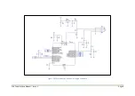
Страница 8: ...CDV Construction Manual Issue 3 Page 8 Figure 1 Microcontroller and power supply schematic ...
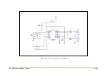
Страница 9: ...CDV Construction Manual Issue 3 Page 9 Figure 2 Si5351A Clock generator schematic ...
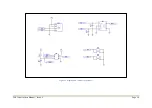
Страница 10: ...CDV Construction Manual Issue 3 Page 10 Figure 3 Display and controls schematic ...
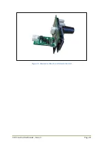
Страница 30: ...CDV Construction Manual Issue 3 Page 30 Figure 11 Attenuator filter board fitted to the CDV ...

