background image

15

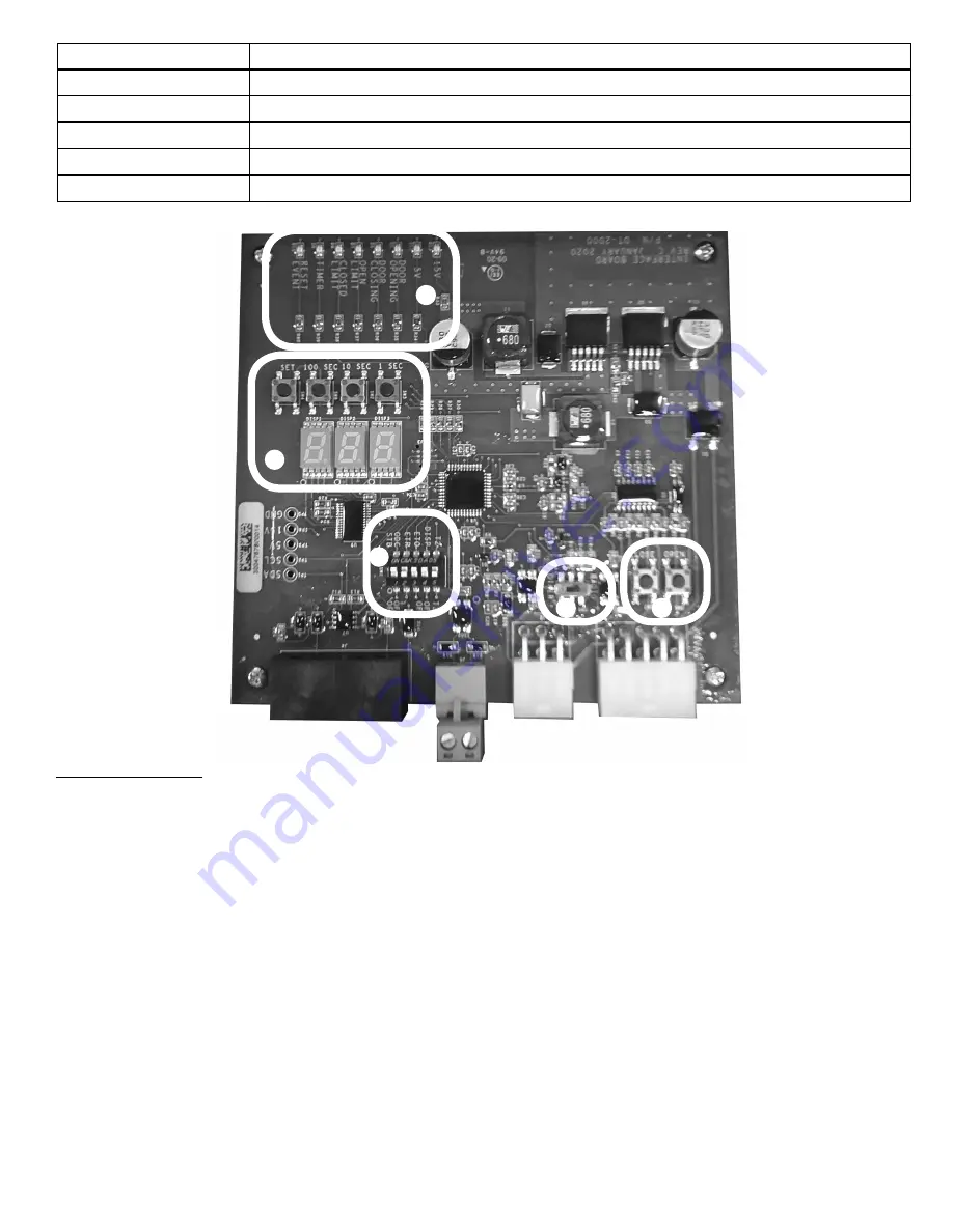
INTERFACE SECTIONS

CONTROLS

A

Activity LEDs. LED will light to show current state of operator and timer.

B

Timer Countdown set and display.

C

Programming Dip switches. Sets various controls for operator and interface.

D

External Radio control. Set on or off depending on active external radio control.

E

OPEN & CLOSE. Press for open or close operator function.

A

B

C

D

E

Normal Operation

Once the system has been setup, the door allay will display the time to close value on the digital display every 

time the door is completely opened. The timer will start at the programmed values and countdown to “1”, 

followed by a flashing “CLSE” message indicating that the door is closing. This is the case whether the door 

is opened by use of an external remote control or through a wired set of pushbuttons if active ETO & ETR 

switches.

If the door is wired with a three-push button switch, the countdown timers will function normally if the timer 

cycle is allowed to run to completion. If the CLOSE button is pressed during the countdown sequence, the 

door close sequence will commence immediately and the countdown value on the display will switch to the 

“CLSE” message until the door is fully closed.

If the STOP button is pressed while the door is open, a “STOP” message will appear on the display for several 

seconds and the countdown value will disappear. The door will remain open indefinitely until the STOP mode 

is terminated. This can be done by pressing the CLOSE button or a remote control button. This will re initiate 

the countdown timer sequence and the door will close once the sequence reaches zero.

Содержание COUNTDOWN TIMER

Страница 1: ...COUNTDOWN TIMER INSTALLATION MANUAL 113047 00108 07 2020...

Страница 2: ...areil est conforme aux CNR d Industrie Canada applicables aux appareils radio exempts de licence L exploitation est autoris e aux deux conditions suivantes 1 l appareil ne doit pas produire de brouill...

Страница 3: ...se kit 111087 0005 S 3ph kit 111087 0006 S 575V 3ph kit Opener will require an external receiver if using remote controls for countdown operation DO NOT use internal receiver with this Countdown Timer...

Страница 4: ...rvice representative must correct the condition causing the malfunction 5 The Operator Motor is protected against overheating by an internal thermal protector If the motor protector is tripped a train...

Страница 5: ...suivre ou d importants l ments prendre en consid ration AVERTISSEMENT DANGER POTENTIEL EFFET PR VENTION PORTE EN MOUVEMENT AVERTISSEMENT Pourrait entra ner des blessures graves voire la mort Utiliser...

Страница 6: ...ounting outside building or in damp conditions it is highly recommended to apply a bead of silicone caulking around rear panel and rear panel screws 7 Install mounting brackets to main housing to best...

Страница 7: ...is more than 3 feet away from operator additional wires and connections will be required to lengthen wires This junction box must be mounted indoors When display is to be mounted outside or in damp lo...

Страница 8: ...8 THIS PAGE INTENTIONALLY LEFT BLANK...

Страница 9: ...the operator must meet all local building codes Overhead Door Corporation recommends that all work involving electrical circuits and line voltage wiring be performed by a qualified electrician AVERTI...

Страница 10: ...CAT5 cable into J4 connector on circuit board 4 Plug CAT 5 cable from second display if used into J4 connector on circuit board CONNECT INTERFACE TO DISPLAY PANEL CAT 5 Display Cables Remove knockouts...

Страница 11: ...e junction box for control harnesses 2 Plug 6 and 10 conductor harnesses into J2 J1 connectors on interface board 3 Route wire into operator using cord grips or conduit 4 ONLY use low voltage inputs t...

Страница 12: ...E MONITORED SAFETY N O REVERSE N A N O REVERSE YELLOW SEE NOTE 1 N O SAFETY EXT INTLK N A EXT INTLK BROWN INTERLOCK J18 AC POWER CONNECTION YELLOW BLACK 24V POWER BLACK BLACK 24V POWER Install 4 forke...

Страница 13: ...DISPLAY INTERFACE DIGITAL DISPLAY J4 J3 J2 J1 RADIO POWER RELAY COMMON CAT5 CABLE GREEN BLUE RED WHITE PURPLE ORANGE YELLOW BROWN BLACK BLACK YELLOW BLUE WHITE WHITE BLUE BLACK WHITE WHITE BLACK WHIT...

Страница 14: ...door is on the DOWN limit LED 7 TIMER Flashes when countdown timer is activated and counting LED 8 RESET EVENT Flashes when a timer initiate input is activated SECTION C GENERAL PROGRAMMING Section C...

Страница 15: ...the door is opened by use of an external remote control or through a wired set of pushbuttons if active ETO ETR switches If the door is wired with a three push button switch the countdown timers will...

Страница 16: ...et and the countdown sequence will be restarted Message is displayed if the system interlock is enabled and a lockout condition has occurred This message will be constantly displayed until INTLK condi...

Страница 17: ...NE FOR SPECIAL INDIRECT COLLATERAL PUNITIVE INCIDENTAL OR CONSEQUENTIAL DAMAGES even if Overhead Door Corporation has been advised of the possibility of such damages Such excluded damages include but...

Страница 18: ...E PCB 113080 0001 S HARNESS KIT 1 each 6 wire 10 wire 113081 0001 S CONNECTOR KIT CAT 5 Standard Watertight included 113082 0001 S CABLE CAT 5 1FT 113082 0002 S CABLE CAT 5 25FT 113083 0001 S KIT BRAC...

Страница 19: ...19 NOTES...

Страница 20: ...The Overhead Door Corporation 1 Door Drive Mount Hope Ohio 44660 1 800 275 6187...

Отзывы: