7
3.1.3. Level sensor’s signals entry to appropriate
inputs and transforms to optimal for further processing
electrical signals.
3.1.4. There are stepped commutators X2 (X3, X4)
in every channel of the device. They are electroconductivity
sensitivity regulating devices of level monitoring channels.
So SAUM6 device can work with different fluid mediums.
3.1.5. Threshold devices are destined to fix when
the fluid level is as high as conductometric sondes (given
levels) and to signal by lighting up LEDs LEVEL. Apart from
that threshold devices generate signals for output relays
control.
3.1.6. Output relays are destined to control external
equipment. External equipment supports performance of
the level monitoring engineering process. Operation of
relay will happen if appropriate signal electrode contacts
with the fluid.
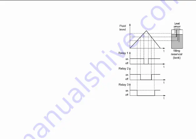
The mode of relay’s behaviour in every channel
may be changed by the user using commutators X5 (X6,
X7), pic. 1. It may be used for functionality enhancement
of the device. Depending on relay’s commutator output relay can become “on” or “off” when sensor’s
electrode contacts with the fluid.
The time history of output relay’s working when all relays become “off” if level sensor’s signal
comes is given in pic. 3.
Pic. 3
Содержание SAU-M6
Страница 20: ...19 Appendix A CONNECTION DIAGRAM...
Страница 21: ...20 Appendix B DIMENSIONS...


