outdoorlink smartlink SL-2-DC-001 Скачать руководство пользователя страница 4


© 2021 OutdoorLink, Inc. | Updated 5.1.2021                                                                                           (256) 885-9768 | www.outdoorlinkinc.com 

(256) 885-9768 | www.outdoorlinkinc.com  


Image 2 


6.


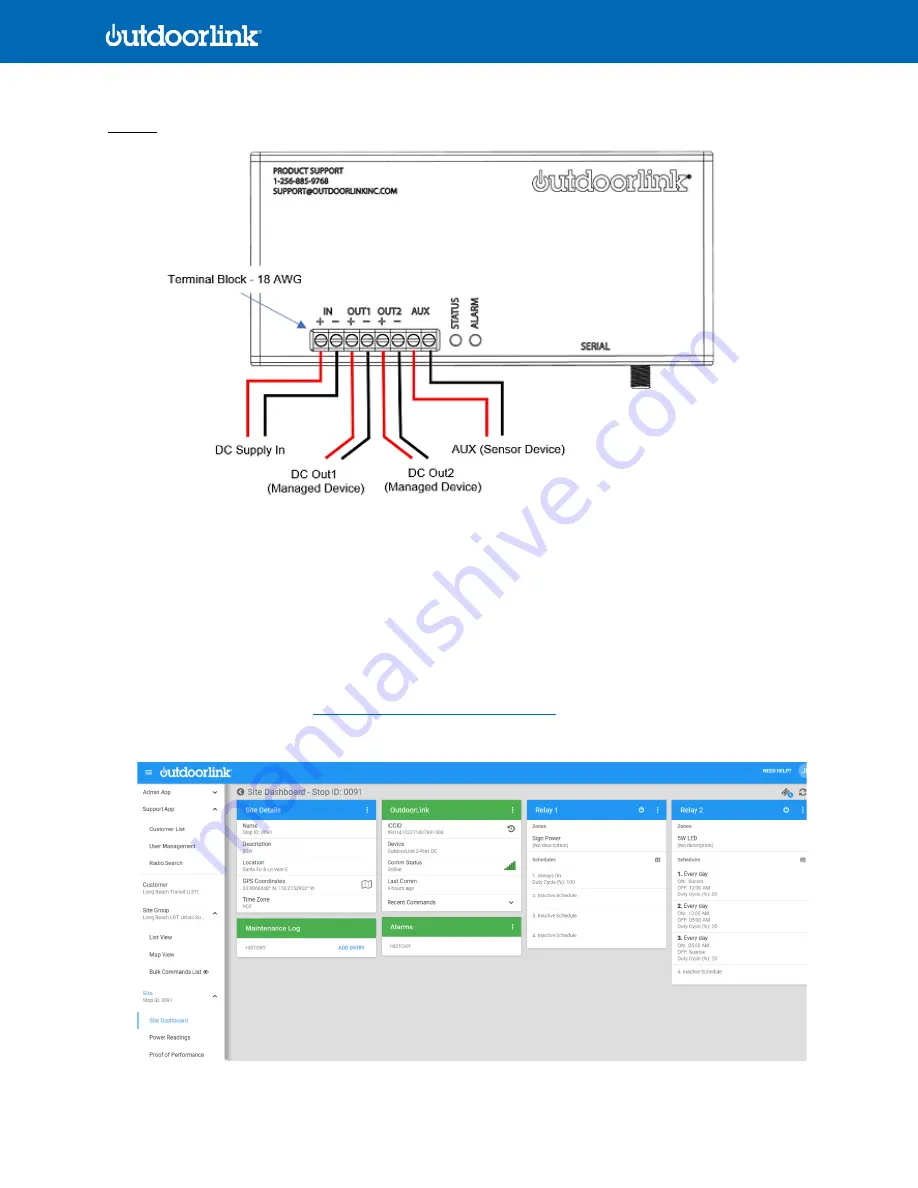
Connect the POS and NEG power supply lines to the IN terminal block with 18AWG wire.  If using an AC power supply, 
then a wiring harness should be supplied to connect the female and male barrel connectors of the adapter.   

7.


Once power is connected to the controller, a green light should start flashing quickly.  If the light is flashing slowly, 
then the SIM card is still reconnecting to its cellular carrier.  

8.


Connect the devices to OUT 1 and OUT 2.  Do this by either directly hardwiring the devices with 18AWG POS and NEG 
wire or use an OutdoorLink supplied wiring harness with barrel connectors.  

9.


Devices will not turn on unless the schedules are assigned to be ON at the time of installation in the SmartLink portal.  
To do this, login to the portal

https://portal.outdoorlinkinc.com/login

search for the last 4 digits of the ICCID number 

on the SmartLink controller

, and go to the unit’s Dashboard


Содержание smartlink SL-2-DC-001

Страница 1: ...al Specifications Device Management Manages up to 2 DC devices per controller Runtime Settings Automatic Sunrise to Sunset and or Manual Time Scheduling Enclosure Polycarbonate 6 x 3 x 1 in approx 15 2 x 7 6 x 2 5 cm Input Voltage Two independent inputs 8 30Vdc 3A each Output Voltage Two independent outputs 5 30Vdc per output 3A each Power Consumption 0 15 W or 0 01 A Connectivity LTE cellular con...

Страница 2: ... solar powered Below is a summary of interface options however not all features apply to all installations Image 1 SL 2 DC 001 Interface Index 1 Terminal Block IN 2 Terminal Block IN 3 Terminal Block OUT1 4 Terminal Block OUT1 5 Terminal Block OUT2 6 Terminal Block OUT2 7 Terminal Block Temp AUX 8 Terminal Block Temp AUX 9 USB 2 0 Micro B Female 10 RJ45 to Serial Female 11 Connector for optional e...

Страница 3: ... Input to the SmartLink and a down converter should be used to convert the higher voltage to the lower voltage device i e 12Vdc 3 Choose installation placement and confirm cable lengths are sufficient for making all device connections The SmartLink should be facing outward and upward for optimal cellular connectivity 4 Place the SmartLink on the chosen location and use double sided tape or Velcro ...

Страница 4: ... start flashing quickly If the light is flashing slowly then the SIM card is still reconnecting to its cellular carrier 8 Connect the devices to OUT 1 and OUT 2 Do this by either directly hardwiring the devices with 18AWG POS and NEG wire or use an OutdoorLink supplied wiring harness with barrel connectors 9 Devices will not turn on unless the schedules are assigned to be ON at the time of install...

Страница 5: ...ts cellular carrier If the schedule is not set to be on at the time then push the Power Button located on the blue header of each Relay If schedule is set for Always On then the device should turn on once it receives power and connects to its carrier If schedule is not set for Always On and schedule is not on at the time of testing press the Power Button on the header of each Relay to turn the dev...

Страница 6: ...tdoorlinkinc com 11 To confirm incoming voltage and each Relay s load click on the three vertical dots on the header of the OutdoorLink Control Box and select Get Unit Status 12 Go to Power Readings on the left side of the portal and select Live Power to confirm each Relay s load ...

Отзывы: