background image

1.2 Always

- Read this guide in full before installing the product;
- Install the

Therma Cable

system with a regulating device;

- Use copper wires only;
- Perform the mandatory tests described in this guide and record readings on the

table of measures;

- Only use cement or an equivalent binder compatible with floor heating systems

(cement glue, ceramic glue, self-levelling cement);

- Ensure that the black heating cable is completely embedded in cement or an

equivalent binder (cement glue, ceramic glue, self-levelling cement);

- Ensure that the voltage supplied equals the nominal voltage of the

Therma

Cable

system;

- Repair the product only using the

Therma Cable

repair kit available at your

authorized Ouellet Canada Inc. dealer;

- Consult Ouellet Canada Inc.’s team of technical specialists for any questions

or for more information;

- Install

Therma Cable

at temperatures over 5 °C (40 °F).

- Heating cables must be at least 13 mm (1/2”) away from any combustible surface.
- Metal structures or materials used for the support of or on which cables or sets

are installed be grounded in accordance with the Canadian Electrical Code
(CSA C22.1 Section 10 and National Electrical Code).

- Installer of series heating cable sets must inspect and remove damaged or

defective heating cable sets before they are covered or concealed;

- Installer of series heating cable sets must mark the appropriate circuit breaker

reference (label) indicating which branch circuit supplies the circuit to those
electric heating cables.

1.3 Never

- Install

Therma Cable

sections so that the heating cables are less than 76 mm

(3”) from each other. The temperature could be too high and could cause
damages;

- Shorten or alter any part of the heating cable (fig. 1.3);
- Cross, overlap, or stack heating cables (they must not touch);
- Connect a 120V product to a 240V/208V power source;
- Use a bending radius under 20 mm (3/4”);
- Install a temperature regulator (thermostat or other) where it is accessible from

the shower or bath (install at least 1 m [3’ 4”] away);

- Staple heating cable or floor sensor end to the subfloor (fig. 1.3);
- Install the

Therma Cable

system if the safety seal is broken;

- Install the

Therma Cable

system under a closet or fixed items.

- Series heating cable sets shall not extend from beyond the room or area in

which they originate;

- Series heating cable sets are not to be installed in walls.

6

N

ev

er

cu

t the

heatin

g

ca

b

le

N

e

ve

r

st

ap

le

th

e h

eating cable

to

th

e

su

b

flo

o

r

N

e

ve

r

st

ap

le

th

e f

loor sensor to

th

e

su

b

flo

o

r

D

o

n

o

t

la

y

he

avy items on

th

e

ca

b

le

Fig. 1.3

Содержание Therma Cable

Страница 1: ...INSTALLATION GUIDE October 2009 Edition...

Страница 2: ......

Страница 3: ...2 4 1 Planning Work 12 4 2 Preparing the Subfloor 13 4 3 Marking the Floor 13 4 4 Installing the Therma Cable Floor Heating System 14 4 5 Installing the Temperature Sensor 17 4 6 Applying Self Levelli...

Страница 4: ...racteristics The Therma Cable system can be installed under a shower floor only if the floor is ceramic or natural stone A waterproof membrane must be used to maintain the heating cables in a dry envi...

Страница 5: ...heating cable junction cold lead channel strapping cold lead plywood or concrete slab strapping heating cable self levelling cement cement glue floor covering aluminum sheath ground wire heating wire...

Страница 6: ...ating cable sets must inspect and remove damaged or defective heating cable sets before they are covered or concealed Installer of series heating cable sets must mark the appropriate circuit breaker r...

Страница 7: ...4 720 19 0 OTR0842 280 85 34 70 6 5 93 8 7 840 16 2 OTR0962 320 97 54 80 7 4 107 9 9 960 14 2 Product 240V 208V Length Surface12W sq ft Surface 9 W sq ft Power Resistance ft m sq ft sq m sq ft sq m Wa...

Страница 8: ...e been correctly noted A qualified electrician must measure the system s insulation resistance as follows Use a calibrated megohmeter only Measure insulation resistance at the free end of the cold lea...

Страница 9: ...easure the system s resistance as follows Use a calibrated multimeter only Measure resistance at the free end of the cold lead between the two phase conductors Write the reading in the measures table...

Страница 10: ...Warming This type of heating is designed to enhance comfort and or supplement the room s main heat source It helps keep the floor at a pleasant temperature at all times Installing this type of system...

Страница 11: ...he thermal resistance of the floor covering must not exceed R 1 40 RSI 0 246 There is no such limit for the subfloor Table 3 3 Thermal resistance values for floor coverings The floor covering highligh...

Страница 12: ...Room Layout and Corresponding Therma Cable Product Create a room layout plan to scale for maximum accuracy use the Ouellet Canada Inc form designed for this purpose Identify all stationary elements t...

Страница 13: ...ler only for self leveller The subfloor must be solidly fastened in place to prevent movement The application of a floor levelling product is recommended to prevent future damage to the ceramic caused...

Страница 14: ...placed under these stationary elements The floor temperature sensor must be centered between two parallel heating cables The ideal location is one where it is likely to be away from stationary objects...

Страница 15: ...sition during the pouring of self leveller this strapping is installed at the end after the lacing of the cable The cable can be installed under the ceramic tile of a shower or other wet surfaces the...

Страница 16: ...ing cable must not be shortened neither cut Avoid walking on the Therma Cable system If you must wear soft rubber soled shoes Always start the Therma Cable at least 50 mm 2 from the walls It is import...

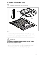
Страница 17: ...lation sheath and a slightly larger diameter than the heating cable The sensor must be embedded in cement or an equivalent binder cement glue ceramic glue self levelling cement Glue the sensor to the...

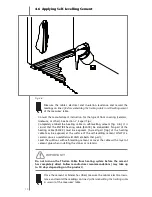
Страница 18: ...BLACK must be exposed A small part top of the heating cable may be exposed at the surface of the self levelling cement ONLY IF a ceramic glue is used afterward AND embeds that part Level the subfloor...

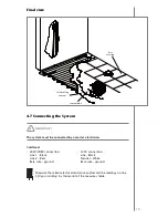
Страница 19: ...208V connection 120V connection Line 1 Black Line Black Line 2 Red Neutral White Bare wire ground Bare wire ground Measure the cable s electrical resistance and record the readings on line 5 Upon inst...

Страница 20: ...be kept near the electrical service If this table is not duly completed the warranty may be annulled Warranty terms are set out in Section 8 4 9 Using the Therma Cable System The Therma Cable floor h...

Страница 21: ...refore a floor covering with greater temperature resistance must be used The room temperature control and floor temperature sensor must never be installed where they will be exposed to sunlight or air...

Страница 22: ...ft 130W sq m at 76 mm 3 spacing is the best watt density to optimize comfort and prevent floor overheating Therma Cable can also be installed with a 100 mm 4 spacing for a 9W sq ft 96W sq m Moreover...

Страница 23: ...carpet be installed over Therma Cable A 14 Yes if the system is completely embedded in self levelling cement You can install low pile carpet over the slab if the carpet s thermal resistance does not e...

Страница 24: ...glue tape 7 2 Floor Covering Tips It is strongly recommended to coat the subfloor with a sealer before spreading the self levelling cement which is very liquid This is to prevent any leaks under the...

Страница 25: ...chaser of the equipments as well as to the subsequent buyer of the building where it has been installed Terms of warranty The present warranties are subject to the compliance of the following terms i...

Отзывы: