background image

7

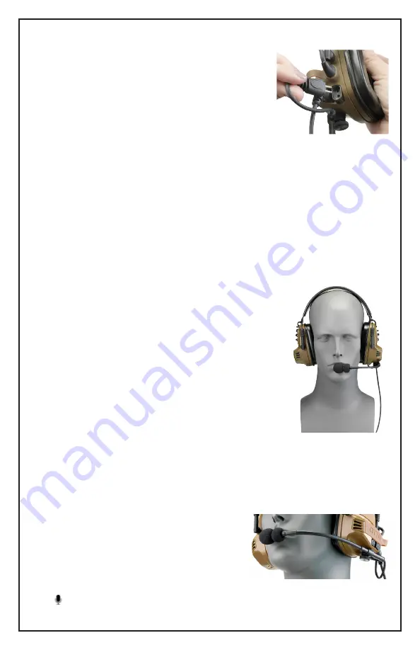
Configuring the Boom Microphone 

(Figures 7 & 8)

The boom microphone is commonly worn on the left side 

but can be installed on either the left or right ear cup. To 

move the mic from one side to the other:
1.  Identify and pull out the two-pin plug that attaches the 

boom mic to the ear cup 

(Figure 7).

2.  Unscrew the knurled screw that attaches the boom 

assembly to the bottom of the ear cup.

3.  Remove the knurled screw from the locking clamp and 

reverse it so that the clamp will position the boom at the 

outboard position on the headset.

4.  Position the boom under the opposite ear cup, and thread the screw in to the ear cup.

5. 

Re-orient the boom so that the mic symbol faces the user’s mouth.

6.  Tighten the knurled screw until boom is secured.
7.  Plug the two-pin plug into the jack at the back of the new ear cup. Note that the rubber 

insert for the plug has an offset shape so that it will only insert in one direction.

Wearing the Headset 

(Figure 9)

(Note: If mounting the headset to the helmet with the op

-

tional Rail Mounting Kit, please see instructions beginning on 

page 10.)

1.  Identify the left and right ear cups. The Power/Volume 

buttons are on the left ear cup.

2.  Place the headset over the head.
3.  Adjust ear cup height by pulling or pushing on the cups 

until the ear seals are securely positioned over the ears. 

Adjustment is accomplished by extending and contract

-

ing the ear cup frames on either side of the ear cups 

while holding the headband in place.

4.  For effective sound protection, be sure that the ear seals 

are completely sealed around the ear and obstacles such as 

hair, jewelry, or clothing are out of the way.

Boom Mic Placement 

(Figure 10)

The boom is flexible and has a length adjustment screw to ensure proper placement for 

effective communications.

1.  Position the boom microphone so that the micro

-

phone is about ¼ inch from the mouth.

2.  To adjust boom length, loosen the screw, position 

the mic at the desired length, and re-tighten.

3.  Position the mic element so that the mic symbol 

 on the boom faces directly toward the user’s 

mouth.

Figure 7

Figure 9

Figure 10

Содержание NoizeBarrier TAC

Страница 1: ...NoizeBarrier TAC Circumaural Headset Technical Manual and Instructions for Use...

Страница 2: ...r s advice for maintenance The thermoplastic polyurethane foam ear seals on the NoizeBarrier TAC may dete riorate with use and should be examined at frequent intervals for damage such as cracking and...

Страница 3: ...NoizeBarrier TAC headset may also be used with the OTTO Multi Port Hub PTT that provides modular control of up to three communications plat forms The Hub is compatible with major radio platforms usin...

Страница 4: ...n page 10 a Headband b Adjustment frames c Audio cross over cable d Ear cups e Comply foam ear seals f Situational awareness talk through microphones g Battery compartment cover h Noise canceling comm...

Страница 5: ...r most helmet systems Proprietary Comply thermoplastic polyurethane foam ear seals allow for secure comfortable fit Ear seals snap in for easy field replacement SCBA compatible connector for gas mask...

Страница 6: ...awareness talk through functions Batter ies are not required for radio communication 1 Identify the rubberized battery covers on the ear cups 2 With finger pressure pry off the battery cover on one ea...

Страница 7: ...Figure 9 Note If mounting the headset to the helmet with the op tional Rail Mounting Kit please see instructions beginning on page 10 1 Identify the left and right ear cups The Power Volume buttons ar...

Страница 8: ...et cable into the Push To Talk PTT cable for your two way radio 2 Attach the cable to the connector on the radio 3 Turn on the radio 4 Receive volume for radio communications is controlled by the volu...

Страница 9: ...edbytheradioiftheheadsetbatteriesaredepletedornot installed Replacing the Ear Seals Figures 12 16 Theearsealsaremountedinaremovableframeforeasyreplacement 1 Removetheearsealbyslidingfingersunder thein...

Страница 10: ...e adjustment frame The frame will unsnap from the reten tion ball on the ear cup Figure 18 3 Repeat the operation on the frame on the other side of the same ear cup 4 Repeat steps 2 and 3 on the other...

Страница 11: ...tward Figure 24 Figure 23 Figure 22 TROUBLESHOOTING Problem Possible Causes Suggested Action Headset will not power on talk through situa tional awareness Depleted batteries Replace batteries Batterie...

Страница 12: ...9 dB EN 352 4 2001 A1 2005 Criterion levels H 115 5 dBA M 107 0 dBA L 96 0 dBA Sound pressure level of external noise for which sound pressure level under the earmuff first exceeds 85 dBA EN 352 6 200...

Страница 13: ...Main Street Carpentersville IL U S A 60110 Toll Free Phone 888 234 OTTO 6886 Phone 847 428 7171 Fax 847 551 1343 E mail info ottoexcellence com www ottoexcellence com 804459 10 19 Information on Dispo...

Отзывы: