


User manual for OTTO HEUSS universal stop motor PCB RM-2
Otto Heuss GmbH
Page
6
of
8
Switch 7:
If this switch is ON, the processor's own temperature sensors are activated. This
automatically switches the magnet off if it gets very hot. Normally this function is
not needed. In "coupler motor" mode, this function is not useful, because the
magnet will most likely become warm or hot during normal operation. To reset after
the temperature shutdown has been triggered, the circuit must be switched off and
on again.
6
Function types / operating modes of the PCB
6.1
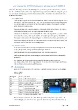
Electrical stop action motor
Usual electrical stop action. There are electric stop switches in the console and additionally
the stop motors in the organ. A permanent ON signal is sent by the setter or stop switch as
long as the stop is ON.
The potentiometer AN [ON], is used to adjust the force (0-100%) of the ON coil.
The potentiometer AB [OFF], is used to adjust the force (0-100%) of the OFF coil.
The push buttons AN [ON] and AB [OFF] on the board can be used to test the set force. To
ensure quieter operation of the motor, the respective "counter-coil" is energized for a short
moment before moving in one direction.
If the button is pressed again, in whose position the magnet is already located, this can be
noticed as a "twitch", as the "counter-coil" is energized again. This can only occur when the
button on the board is pressed and not in the regular working mode of the magnet.
When the organ is switched on, the motors automatically energize one side to match the
ACTUAL state of the sliders to the SET state of the switches.
6.2
Dual electrical / mechanical stop action motor
Combination of electric stop action together with mechanical stop action. There are no
electrical stop switches in the console, only the stop motors which are mechanically
connected to the stop action and slider. The setter sends an ON pulse to the input AN [ON] or
an OFF pulse to the input AB [OFF] to move the motor electrically.
The potentiometer AN [ON], is used to adjust the force (0-100%) of the ON coil.
The potentiometer AB [OFF], is used to adjust the force (0-100%) of the OFF coil.
The push buttons AN [ON] and AB [OFF] on the board can be used to test the set force. To
ensure quieter operation of the motor, the respective "counter-coil" is energized for a short
moment before moving in one direction.
If the button is pressed again, in whose position the magnet is already located, this can be
noticed as a "twitch", as the "counter-coil" is energized again. This can only occur when the
button on the board is pressed and not in the regular working mode of the magnet.
In dual stop action mode, the setter (not this PCB) needs a permanent signal from a switch as
feedback as soon as the register is pulled. This switch can either be fed directly to the setter
separately from the power supply, or it can run over the motor PCB. In this case the switch is
connected to the two connection points "Schalter" [Switch] on the side of the board. The
corresponding signal is given out at the "Kontakt" [Contact] output. The output voltage
corresponds to the applied supply voltage.


