


User manual for OTTO HEUSS universal stop motor PCB RM-2
Otto Heuss GmbH
Page
3
of
8
3
Mechanical connection
3.1
Mounted PCB
The mounted circuit is usually supplied by us fully assembled and wired. The designation of
the connections can be read when the white plug is removed.
The mounted circuit is mounted on the motor by four PCB holders. The four connecting cables
of the motor are connected to the corresponding terminals MAGNET AN/COM/COM/AB.
On the PCB there are arrows next to the potentiometers marked AN (ON) and AB (OFF). These
indicate the working direction of the motor. This can also be inverted by means of dip switch
3, as described later.
3.2
Plug-In PCB
The plug-in circuit is plugged into the corresponding slot of the control cabinet.
Attention:
For safe insertion and removal of the card, make sure to switch off the organ! The wiring of
the motors to the switch cabinet is described in the respective manual of the switch cabinet.
4
Electrical connection
4.1
Mounted PCB
All connection terminals are designed with push-in connection technology. This allows rigid
conductors or flexible conductors with cable shoes to be inserted into the terminal without
actuating the release-button. To release the cable or to insert flexible conductors without cable
shoes, the release-button must be actuated.
For the white 4-way terminals, the release is the orange actuating surface above. On the
black/red terminals, the release is the slot-shaped recess between the two cable entries
located above each other.
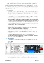
The red/black connector is not removable, the designation of the terminals is printed next to
it on the board. The connection terminal is intended for cables up to 2.5mm².
The black terminal is labeled "-" and intended for the negative connection (=GND), the red
terminal is labeled "+" and intended for the positive connection. The second cable slot can be
used to build a cable bridge to the next motor.
Attention:
When +/- connecting several PCB´s, please note the required fuse and the cable diameters
that depend on it!


