Otto Bock Start M4 XXL Скачать руководство пользователя страница 16

6.6 Adjusting the back support

6.6.1 Adjusting the back support height

The back support height is adjustable by 

75 mm

. The back support height is set by moving the back support tubes

in the central unit in increments of 

25 mm

.

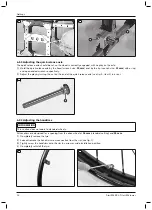
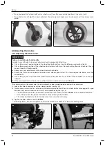
1)  Remove the drive wheels and secure the wheelchair by jacking it up.
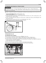
2)  Remove all Allen head screws from the vertical attachment device of the central unit (see fig. 18).
3)  Slide both back support tubes to the desired height. Both back support tubes must be set to the same height.
4)  Reinsert all Allen head screws on the central unit and tighten them with the following tightening torques:

Allen head screws at item 1: 

8 Nm

Allen head screws at item 2: 

10 Nm

5)  When adjusting the maximum back support height, an additional screw connection with plastic spacers has to

be  mounted  in  the  uppermost  bore  hole  of  the  central  unit  (see  fig. 18,  item 3).  This  is  part  of  the
“481D53=ST170 conversion kit for standard back support tube”.

18

6.6.2 Adjusting the back support angle

Adjusting the back angle is described in more detail in the included instructions for use (user).

6.7 Adjusting the back support upholstery / seat upholstery

6.7.1 Adjusting the back support upholstery

INFORMATION

A well-adjusted back support provides lasting comfort for the wheelchair user and reduces the risk of secondary
damage and pressure zones.

INFORMATION

Ensure that the user’s pelvis is positioned as far back in the wheelchair as possible, i.e. between the back sup­
port tubes.

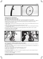
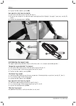
The adjustable back support upholstery can be adapted in segments to the needs of the user. 
1)  Remove the seat cushion.
2)  Pull the back support pad up and off the hook-and-loop fastener on the back support upholstery.
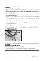
3)  Loosen  the  back  support  straps  and  use  the  hook-and-loop  fastener  to  fasten  them  with  the  desired  tension

(see fig. 19). 

4)  Put on the back support pad and attach it to the hook-and-loop fastener on the back support upholstery.
5)  Put on the seat cushion and secure it with the hook-and-loop fastener.

16

Settings

Start M4 XXL, Start M6 Junior

Содержание Start M4 XXL

Страница 1: ...Start M4 XXL Start M6 Junior Instructions for use qualified personnel 3...

Страница 2: ...2 Start M4 XXL Start M6 Junior...

Страница 3: ...ng the wheel locks 6 4 1 14 Adjusting the braking force of the drum brake 6 4 2 15 Adjusting the seat 6 5 15 Adjusting the seat depth 6 5 1 15 Adjusting the back support 6 6 16 Adjusting the back supp...

Страница 4: ...nformation 9 1 24 Information on re use 9 2 24 Legal information 10 24 Liability 10 1 24 Warranty 10 2 25 Service life 10 3 25 Technical data 11 25 Appendices 12 29 Required tools 12 1 29 Torque value...

Страница 5: ...ctions for use user These instructions for use must be given to the user The manufacturer recommends checking the product settings regularly in order to assure an optimum fit over the long term A revi...

Страница 6: ...ing Damage to the product caused by transportation using incorrect packaging Use only the original packaging for delivery of the product 3 3 Safety Instructions for Assembly WARNING Changed diameter i...

Страница 7: ...ek of manufacture PP production site XXXX sequential production number 2 YYYY year of manufacture MM month of manufacture DD day of manufacture 3 UDI PI to GS1 standard UDI Unique Device Identifier PI...

Страница 8: ...lding the wheelchair out or together only grip by the specified components CAUTION Failure to verify readiness for use before putting into operation Tipping falling due to incorrect adjustment or inst...

Страница 9: ...uts with new self locking screws and nuts after disassembly Adjustments to match the concrete physical and mental condition of the user should always be made in the user s presence All parts of the pr...

Страница 10: ...es of the fitting to 50 Nm INFORMATION After adjustment the distance of the left and right fittings to the side panel must be the same 6 Check the depth setting Both sides must be positioned exactly t...

Страница 11: ...ee fig 3 item 3 3 Slide the drive wheel adapter to the desired height position 4 Reinsert and tighten the mounting screws to 10 Nm 5 Check the height setting Once changed the left and right drive whee...

Страница 12: ...nut on the end of the quick release axle see fig 5 item 1 in or out 5 6 2 4 Adjusting the handrims INFORMATION This section does not apply to standard wheels All handrims are designed for a spacing f...

Страница 13: ...earing perpendicular to the ground see fig 11 item 3 6 Tighten the Allen head screws to 8 Nm 7 Reinstall the caps see fig 10 item 1 The caster axle on each of the two caster journal bearings must be p...

Страница 14: ...to do so must not exceed 60 N Check the tyre pressure of the drive wheels Note the information in the section Technical data or on the tyre sidewall Only use original drive wheels with a verified maxi...

Страница 15: ...raping noise at the rear wheel disappears and the wheel runs freely 3 Tighten the counter nut see fig 16 item 1 until the adjustment screw is fixed The braking force of both rear wheels must be adjust...

Страница 16: ...t for standard back support tube 18 6 6 2 Adjusting the back support angle Adjusting the back angle is described in more detail in the included instructions for use user 6 7 Adjusting the back support...

Страница 17: ...p fastener on the bottom of the seat upholstery see fig 21 5 Push the seat upholstery onto the crossbrace 6 Slide on the protective caps 7 Unfold the wheelchair In doing so the crossbrace must be seat...

Страница 18: ...head screws on the foot plate see fig 26 item 1 2 Turn the foot support to the desired angle see fig 26 item 2 3 Tighten the Allen head screws to 6 Nm Continuous leg support 1 Loosen the Allen head s...

Страница 19: ...the support angle of the amputation leg support The angle adjustment is carried out in the same way as for the elevating leg support For additional information see the instructions for use user Adjus...

Страница 20: ...nel tube INFORMATION In this step the depth of the forearm support can also be adjusted 4 Insert and firmly tighten both Allen head screws see fig 31 31 32 Plug on side panel 1 Adjusting the height of...

Страница 21: ...base and a backrest that is tilted far back an anti tipper may need to be installed on both sides depending upon the user s experience Verify that the anti tipper has been installed and adjusted prope...

Страница 22: ...37 item 1 2 2 Slide the Allen head screws in the slotted hole of the attachment plate until the pivot point of the anti tipper clamp is aligned with the outer diameter of the tyre see fig 37 item 3 3...

Страница 23: ...ping jaws and star handles see fig 38 item 1 Installation is described in more detail in the supplied instructions for use reference number 647G367 Attaching the head support 1 Open the clamp bracket...

Страница 24: ...Disposal 9 1 Disposal information All components of the product must be disposed of properly in accordance with the respective national environ mental regulations 9 2 Information on re use CAUTION Us...

Страница 25: ...turer General information Start Max load kg M4 XXL 160 M6 Junior 90 Max load with use in a vehicle for transport ing persons with reduced mobility kg M6 Junior 75 Transport weights for seat width of 4...

Страница 26: ...art M6 Junior 490 Rear seat height mm Start M4 XXL 380 Start M6 Junior 370 Start M4 XXL 500 Start M6 Junior 490 Back support angle 0 vertical Start M4 XXL 35 Start M6 Junior 306 Back support height mm...

Страница 27: ...irs in operational condition is 700 mm This specification should ensure unimpeded use of emergency exits and trains for example Please note that the actual wheelchair dimensions may exceed the recomme...

Страница 28: ...M6 Junior Drive wheel size Setting range 20 370 430 22 380 450 24 410 490 1 The values indicated are rounded values which have been theoretically determined Max deviation 10 mm The front seat height d...

Страница 29: ...ded wrenches in sizes 10 11 13 19 and 24 Set of screwdrivers Torque wrench measurement range 5 50 Nm Tyre lever Tyre pump 12 2 Torque values of the screw connections Unless otherwise specified screw c...

Страница 30: ...Start M4 XXL Start M6 Junior 30...

Страница 31: ...T 90 212 3565040 F 90 212 3566688 info ottobock com tr www ottobock com tr Africa Otto Bock Alg rie E U R L 32 rue Ahc ne Outaleb Coop rative les Mimosas Mackle Ben Aknoun Alger DZ Alg rie T 213 21 9...

Страница 32: ...late Version SB_2016 10 21 FM483 SB_210x297 Ihr Fachh ndler Your specialist dealer Otto Bock Mobility Solutions GmbH Lindenstra e 13 07426 K nigsee Germany www ottobock com Ottobock 647G324 en_INT 05...

Отзывы: