


operation (continUeD)
Blade Welding
Refer to Figures 5 and 9.
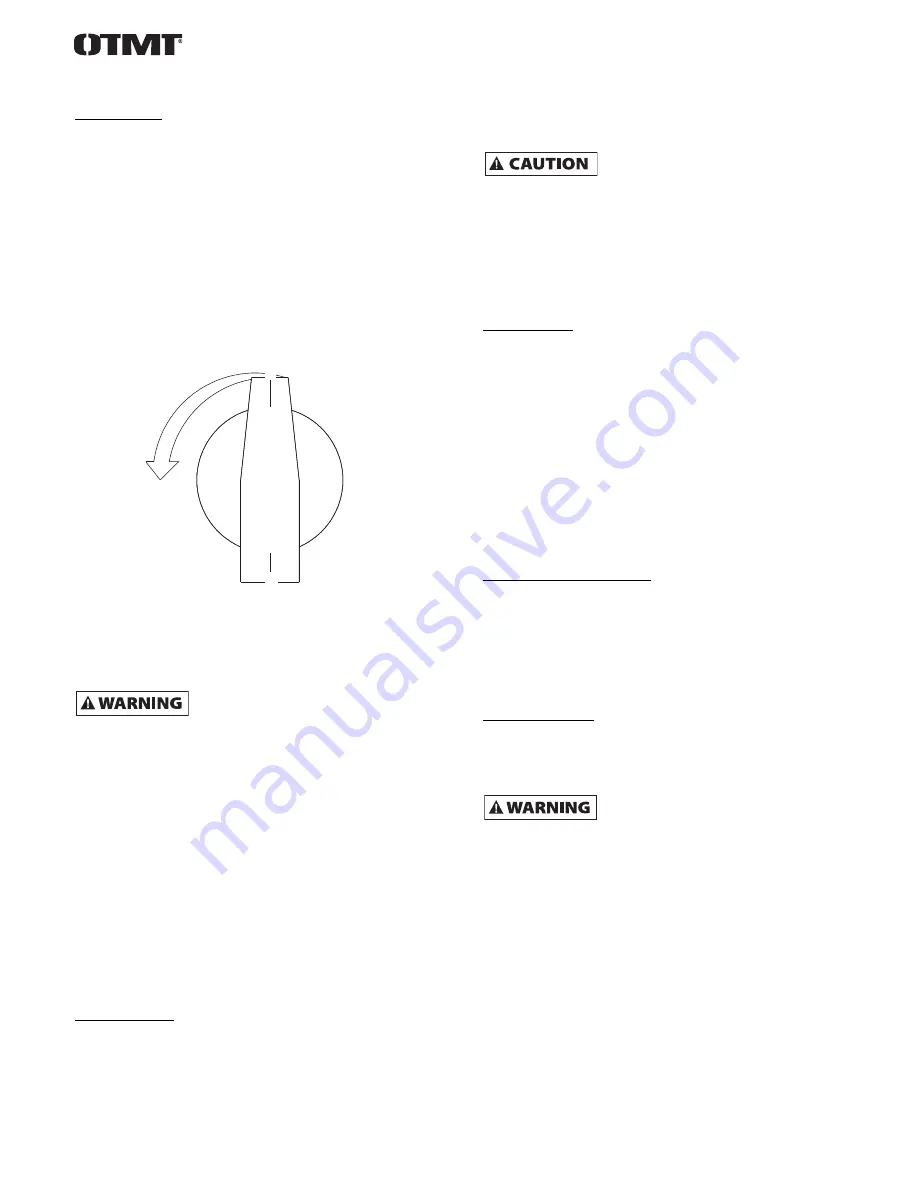
To set weld pressure adjustment knob, turn the knob
counterclockwise to increase the pressure. The pressure
adjustment knob controls force applied to the movable jaw.
NOTE: Weld pressure adjustment knob must be reset to “0” after
each welding.
Wider blades and thicker blades need more weld pressure to force
the blade ends together during welding. If too little pressure is
applied, the blade ends will melt. Too much pressure may cause
the blades to overlap.
For example, for 1/2" wide blades, turn the pressure adjustment
knob counterclockwise until the pointer is at 6 (See Figure 9).
If blade melts, increase pressure. If there are "blow holes" in the
weld, increase pressure. If blade overlaps, decrease pressure. Wider
blades need more pressure and thinner blades need less pressure.
Weld pressure is also affected by blade material.
Welding operation produces sparks at blade
intersection. Step away to left side of welder
during welding operation.
To complete welding operation, flip spark deflector down. Step to
left side of welder. Press weld button and hold down. The blade
ends will become red hot and soft. The movable jaw will force the
blade ends together creating a bead of metal and the limit switch
will automatically cut power to jaws. Release weld button and wait
10 seconds to allow blade to cool. Reset weld pressure adjustment
to “0”.
Heat build-up in the tool can cause serious damage to the tool.
Allow transformer to cool down to room temperature between
each welding or each annealing operation.
IMPORTANT: Let the transformer be idle for at least 3 minutes
between successive welding/annealing operations.
Insufficient cooling time can also result in inaccurate movable jaw
retraction, causing defective weldments.
Blade annealing
After the blade has been welded, the weld area will be very hard
and brittle. Before the blade can be used, it must be annealed and
the flash removed.
The blade weld is annealed by heating the blade just under the
melting temperature and then slowly cooling the weld.
NOTE: Reset weld pressure adjustment knob to “0” prior to
annealing. Failure to do so can cause damage to transformer.
Press the anneal button until the weld area glows a cherry red and
then release the anneal button.
The blade weld will melt, destroying the weld,
if the anneal button is not released as soon as
the weld glows cherry red.
Let the blade cool for several seconds . Press the anneal button
again, but release the button before the weld glows as brightly as
the first time. Wait several seconds until the blade cools further.
Repeat the anneal process 6 or 7 times, decreasing the anneal
temperature each time. The weld flash must be ground from the
blade. See “Grinding Blade”.
grinding Blade
After annealing the blade, the metal buildup or flash must be
ground from the blade.Toggle grinder switch to the ON position.
Flip the grinder guard open, exposing the top of the grinding
wheel.
Weld should be ground to same thickness as blade. Grind flash off
under-side of blade taking care not to grind into blade.
Turn blade inside out and grind the other side of the blade the
same as the first side (or, flip the grinder guard to the closed
position and use the bottom of the wheel). Take care not to grind
into blade. Turn blade inside out again (to original shape).
Turn grinder off when grinding is completed. The blade must be
annealed again.
anneal Blade after grinding
After flash has been removed, anneal the blade a second time. The
weld may have been hardened by heat created during grinding.
Repeat “Blade Annealing” step.
After second blade annealing operation, the blade is ready for
installation onto band saw. Follow Band Saw Instruction Manual
when installing and adjusting blade.
clean Welder Jaws
After each welding operation, wipe welder jaws clean of any oil,
dirt or rust and scrape any flash deposited on welder jaws.
maintenance
Make certain unit is disconnected from power
source before attempting to service or remove
any component. If power cord is worn, cut, or damaged in any way,
have it replaced immediately by a qualified electrician.
Welder jaws must be kept clean at all times. The jaws must be
wiped clean of any dirt or oil and scraped clean of flash after each
weld.
The shear blades should be wiped with an oily cloth to remove any
dirt or rust.
To replace grinding wheel, remove two screws holding grinder
guard and remove guard (Figure 11, Ref. Nos. 7 and 58). Hold
grinding wheel stationary and remove nut and washer (Ref. Nos. 4
and 5). Install new wheel on grinder motor shaft and fasten with
washer and nut. Make sure nut is tight. Attach grinder guard with
two screws.
6
figure 9 – Weld pressure adjustment
0
1
2
3
4
5
6
7
8
9