background image


10279-D01-00 

Page 79 of 142 


This information is the property of Oshkosh Specialty Vehicles and is considered to be confidential. The contents may not be used, either 
partially or wholly, for any purpose inconsistent with which it was produced. This information may not be reproduced or disclosed without prior 
express consent. 

9.5 System 

Operation 

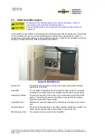
The humidifier is an integral part of the HVAC System. The humidifier system is capable of 
producing up to 12 pounds of steam per hour, at 15 amps. A sensor continually monitors the 
interior of the mobile unit for relative humidity. This sensor is located in the HVAC return duct and is 
programmed to keep the relative humidity at 50%. If the humidity drops below the set point, the 
humidifier is signaled to emit more steam. The humidifier creates steam when electrodes in the 
steam cylinder of the humidifier vaporize the supplied water. The steam then travels through a 
hose to a distribution pipe located in the return air duct of the HVAC system. Since the steam is 
injected into the return duct of the HVAC system, both A/C units are supplied with humidified air for 
distribution throughout the interior of the mobile unit. If for any reason the airflow is disrupted, the 
humidifier will shut down. When the sensor detects that relative humidity has been reached, a 
signal is sent to the humidifier to stop it from creating more steam. The “Humidity Warning” light will 
illuminate on the system panel if the humidity inside of the mobile unit becomes too high or too low. 
If this happens, please refer to 

Appendix B: Troubleshooting

 of this manual. 

9.6 Water 

Supply 

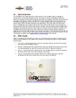
Water is supplied to the humidifier by means of an onboard water supply tank. The water supply 
tank can only be filled from the outside of the mobile unit. Plumbing connections at the humidifier 
are as follows: 

1.  A ¾” G.H.T. male threaded hose connection is located under the front kick of the mobile 

unit, below the air conditioning units. 

2.  One 0.5” outer diameter PVC drain line from the steam cylinder for automatic drain cycles. 

The drain penetrates the floor of the mobile unit in order to empty to the exterior. 

3.  One 0.5” outer diameter PVC drain line from the humidifier cabinet. The drain penetrates 

the floor of the mobile unit in order to empty to the exterior. 

4.  One 0.5” outer diameter PVC overflow drain from the water supply tank. The drain 

penetrates the floor of the mobile unit in order to empty to the exterior. 


Figure 43: Humidifier External Water Connection 


Содержание SIEMENS ESPREE 1.5T

Страница 1: ...hout the written permission of Oshkosh Specialty Vehicles This manual may be used only by you and only for the purposes for which it was intended You may not disclose this manual or the confidential i...

Страница 2: ...ts driving dangerously driving while under the influence of alcohol or drugs driving without a valid operators license or insurance or driving without due care or any illegal action by the driver may...

Страница 3: ...s and materials of the product described herein If there are any inconsistencies between this manual and the mobile unit that inhibit serviceability please contact Oshkosh Specialty Vehicles for assis...

Страница 4: ...llows and be alert to the possibility of personal injury or death Electrical mechanical pneumatic and hydraulic safety devices have been installed on this vehicle to help protect against personal inju...

Страница 5: ...e Unit Overview 19 3 1 Air Ride Control Valves 19 3 2 Canopy optional 20 3 3 Control Room Overall 21 3 4 Cryogen Compressor 22 3 5 Equipment Room Overall 23 3 6 Exterior Overall 24 3 7 Exterior Staff...

Страница 6: ...Install the Rear Stabilizing Stands 52 5 5 Re level the Mobile Unit 52 5 6 Disconnect the Tractor Air and Electrical Lines 52 5 7 Lower the Auxiliary Support Legs 52 5 8 Install the Stair Assembly 53...

Страница 7: ...ounding Note 70 Section 8 Generator 71 8 1 Generator Stop Start Selector 73 8 2 Unit Power Selector 73 8 3 480V AC FAULT Indicator Light 73 Section 9 HVAC System 75 9 1 Air Conditioning Chiller 76 9 2...

Страница 8: ...98 Magnet Room 98 13 4 Warning Lights 99 Power Warning Light 99 Transport Warning Light 100 Transport Warning Strobe Light 100 Section 14 General Maintenance 101 14 1 Daily Maintenance 101 14 2 Weekly...

Страница 9: ...es 125 Machine or Equipment for this Procedure 125 Control of Hazardous Energy 125 Affected Personnel to notify when the Specialty Vehicles Trailer is to be Locked Out 125 Shut down specifications for...

Страница 10: ...of Oshkosh Specialty Vehicles and is considered to be confidential The contents may not be used either partially or wholly for any purpose inconsistent with which it was produced This information may...

Страница 11: ...Buttons 33 Figure 18 Stabilizing Stands 34 Figure 19 Stair Assembly standard 35 Figure 20 Fresh Water Connection 36 Figure 21 Interlocks 37 Figure 22 Emergency Exit Service Door 38 Figure 23 Emergenc...

Страница 12: ...roduced or disclosed without prior express consent Figure 50 Air Bag Controls 92 Figure 51 Emergency Dual Beam Lighting 93 Figure 52 Compartment Light 94 Figure 53 Drop Light 95 Figure 54 Staff Door L...

Страница 13: ...l is not intended to enable persons unfamiliar with the mobile unit to perform the setup and transport procedures This manual contains the basic information needed to setup transport and service the m...

Страница 14: ...r express consent As part of Oshkosh Specialty Vehicles on going program to improve its products and service and their effectiveness in enhancing safety reliability performance productivity and the us...

Страница 15: ...make sure that eyes are protected while servicing the unit Wear safety goggles when prying drilling grinding or working with batteries Wear safety goggles over regular prescription glasses unless the...

Страница 16: ...uffocation If any personnel inhale gas quickly move them to fresh air and seek medical attention at once 3 The gases used in mobile MRI units to cool the magnet can cause severe frostbite If frostbite...

Страница 17: ...the warning lights are illuminated do not move the mobile unit 3 Before moving the mobile unit verify that all marker and running lights are working properly 4 Consult with the local DMV to determine...

Страница 18: ...of Oshkosh Specialty Vehicles and is considered to be confidential The contents may not be used either partially or wholly for any purpose inconsistent with which it was produced This information may...

Страница 19: ...omponent a picture and description will be found to better illustrate the components of the mobile unit Additional components of the mobile unit can be found within the remaining chapters 3 1 Air Ride...

Страница 20: ...ly or wholly for any purpose inconsistent with which it was produced This information may not be reproduced or disclosed without prior express consent 3 2 Canopy optional This retractable canopy is po...

Страница 21: ...ed either partially or wholly for any purpose inconsistent with which it was produced This information may not be reproduced or disclosed without prior express consent 3 3 Control Room Overall Control...

Страница 22: ...er partially or wholly for any purpose inconsistent with which it was produced This information may not be reproduced or disclosed without prior express consent 3 4 Cryogen Compressor The cryogen comp...

Страница 23: ...partially or wholly for any purpose inconsistent with which it was produced This information may not be reproduced or disclosed without prior express consent 3 5 Equipment Room Overall Equipment Room...

Страница 24: ...holly for any purpose inconsistent with which it was produced This information may not be reproduced or disclosed without prior express consent 3 6 Exterior Overall In these pictures the Platform Lift...

Страница 25: ...t was produced This information may not be reproduced or disclosed without prior express consent 3 7 Exterior Staff Entry Door A 44 inch wide high quality steel positive latching double gasket insulat...

Страница 26: ...ompartment The fuel compartment stores the fuel tank fuel gauge fuel pump and fuel separator Figure 9 Fuel Compartment Fuel Gauge The fuel gauge is push button activated and will give an accurate read...

Страница 27: ...ctions must be made before moving the mobile unit Failure to make all connections can result in damage to the mobile unit Figure 10 Glad Hand Connections Emergency Airline Backup airline in the event...

Страница 28: ...e confidential The contents may not be used either partially or wholly for any purpose inconsistent with which it was produced This information may not be reproduced or disclosed without prior express...

Страница 29: ...used either partially or wholly for any purpose inconsistent with which it was produced This information may not be reproduced or disclosed without prior express consent 3 12 Levels The levels allow...

Страница 30: ...ol Room Lighting and E Stop Roll Door Controls and Platform Lift UP light Scan Room E Stop and Magnet Quench Controls Air Conditioning Trouble Light Alarm Figure 14 Mobile Unit Controls Control Room L...

Страница 31: ...re located in the underbody compartments The connections are used to connect the mobile unit to the shore facility The telephone connections utilize a Hubbell all weather connection while the data lin...

Страница 32: ...ent with which it was produced This information may not be reproduced or disclosed without prior express consent 3 15 Scan Room Overall Scan Room houses the medical equipment system Also located in th...

Страница 33: ...may not be reproduced or disclosed without prior express consent 3 16 Magnet Room The Magnet Room is located at the rear of the magnet and is accessible from the rear service entrance door This room i...

Страница 34: ...ny purpose inconsistent with which it was produced This information may not be reproduced or disclosed without prior express consent 3 17 Stabilizing Stands The stabilizing stands are placed underneat...

Страница 35: ...partially or wholly for any purpose inconsistent with which it was produced This information may not be reproduced or disclosed without prior express consent 3 18 Stair Assembly The stairs allow acces...

Страница 36: ...ed either partially or wholly for any purpose inconsistent with which it was produced This information may not be reproduced or disclosed without prior express consent 3 19 Fresh Water Connection The...

Страница 37: ...e component literature binder Figure 21 Interlocks 4 1 Door Interlock System Scan Room and Magnet Room are shielded from radio frequency interference If doors that lead to these rooms are opened radio...

Страница 38: ...th which it was produced This information may not be reproduced or disclosed without prior express consent 4 2 Emergency Exit Service Door Equipment Room An emergency exit service door has been instal...

Страница 39: ...e emergency lighting system is wired into a 120V AC electrical system that allows the lights internal circuitry to keep its batteries at 100 charge The emergency lights will illuminate the exit doors...

Страница 40: ...ted in Volume II of the literature provided by Oshkosh Specialty Vehicles A standard fire detection system is installed in the mobile unit The fire detection system works via photoelectric smoke detec...

Страница 41: ...lash 4 The HVAC units will shutdown Pull Station A pull station is located next to the staff door in Control Room When the pull station has been pulled the steps outlined above will occur Figure 27 Fi...

Страница 42: ...nal An optional fire suppression system is available for the mobile unit This fire suppression system uses a dispersant to extinguish the fire The dispersant used is a gas that removes the oxygen from...

Страница 43: ...to alarm the fire system control panel will remain in alarm condition until the control panel is manually reset To reset the control panel open the front cover and depress the system reset button If a...

Страница 44: ...med all personnel must vacate the mobile unit as soon as possible Abort Switch The abort switch will not stop the dispersant from discharging indefinitely The abort switch only postpones the discharge...

Страница 45: ...nce Switch 4 7 Gauss Lines The magnetic field created when the magnet is up to full filed attracts objects containing iron steel nickel and cobalt Such objects must not be brought into the exclusion z...

Страница 46: ...objects must not be brought into the exclusion zone area Large objects will not be able to be restrained Persons with implants or prosthetic devices must not enter this area Pacemakers may be disabled...

Страница 47: ...he mobile unit On the exterior of the mobile unit the controls can be found alongside the controls for the Platform Lift On the interior the controls can be found next to the staff door A green indica...

Страница 48: ...hutdowns that can take place on the mobile unit Of the different types both manual and automatic shutdowns exist All shutdowns refer only to the medical system and not the HVAC system unless otherwise...

Страница 49: ...If no other smoke detector goes into alarm the fire system control panel will remain in alarm condition until the control panel is manually reset To reset the control panel open the front cover and d...

Страница 50: ...e magnetic field Depressing the E Stops or A1 Stop buttons will not deplete the magnetic field Manual shutdowns are those that require the operating personnel to depress Emergency OFF buttons in the e...

Страница 51: ...e or insurance or driving without due care or any illegal action by the driver may result in invalidating the Siemens Magnet Technology warranty Due care must be exercised to use the lowest speeds pos...

Страница 52: ...4 Raise the mobile unit high enough to insert the stabilizing stands Move the switch to the OFF position 5 Install the stands under the stand supports 6 After the stands have been installed turn the...

Страница 53: ...erneath the staff door 4 Adjust the height of the stair legs as necessary to in order to level and secure the stairs 5 Install the handrail into its operating position and secure in place with the har...

Страница 54: ...form has been lowered install the handrails and secure them with the hardware provided 5 10 Connect to Shore Power Before connecting or disconnecting from shore power it is imperative that the shore p...

Страница 55: ...wer is good the green indicator labeled 480V AC OKAY will illuminate b If the supply of power is experiencing problems such as being out of phase the red indicator labeled 480V AC FAULT will illuminat...

Страница 56: ...at the faucet 5 This will fill the water tank for the mobile unit 6 In the event that the water tank is overfilled an overflow drain has been provided that exits outside of the mobile unit Fresh Water...

Страница 57: ...cal equipment manufacturer The second type deals with the restraints that are used by the mobile unit manufacturer Various items may be secured while the unit is being transported These items may cons...

Страница 58: ...ts caught or penetrating the tire carcass and for proper inflation Check tire pressure when the tires are cool and maintain the pressure molded into the sidewall Do not operate a trailer with tires th...

Страница 59: ...will enable one person to move the lift into the transport position 4 Lower the lift so that it rests securely in the retaining cradles Make sure that the micro switch is actuated 5 Insert the transp...

Страница 60: ...er and call a certified electrician before attempting to reconnect to shore power When turning the power selector switch from one position to another the selector must be paused for a minimum of five...

Страница 61: ...underneath the staff door 5 Place the stair assembly on the ground 6 Using the sole of your shoe step on the spring loaded release to retract the adjustable legs on each side of the stair assembly 7...

Страница 62: ...7 Disconnect the Water Waste Hoses On the left side exterior of the mobile unit a water connection can be found Be sure to fill the fresh water tank prior to disconnecting the fresh water supply The...

Страница 63: ...he underbody compartment door that stores the rear stabilizing stands 2 Open the left rear underbody compartment where the control panel that contains the switch and lever that controls the air suspen...

Страница 64: ...d with the supplied hardware prior to transporting the mobile unit 2 Are all exterior doors closed and locked If not make sure that all exterior doors are closed and locked 3 Is the Platform Lift in t...

Страница 65: ...r of the mobile unit as well as irreparable damage to the mobile unit Snubbers have been added to various electrical sub systems in order to eliminate scanner image problems The entire electrical syst...

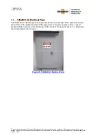
Страница 66: ...ay not be reproduced or disclosed without prior express consent 7 1 120 208V AC Electrical Panel The 120 208V AC electrical panel is responsible for the power supplies to the equipment aboard the mobi...

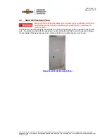
Страница 67: ...2 480V AC Electrical Panel Make sure that all electrical parts are serviced only by a certified electrician or qualified personnel Dangerous voltages are present which could result in injury or death...

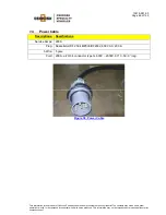
Страница 68: ...ellstoll Ampere Rating 200 A disconnect Model DF 2504 FRAB 0 Ampere Rating 200 A Figure 35 Shore Power Connection Oshkosh Specialty Vehicles Connector The plug that is provided by Oshkosh Specialty Ve...

Страница 69: ...ially or wholly for any purpose inconsistent with which it was produced This information may not be reproduced or disclosed without prior express consent 7 4 Power Cable Descriptions Specifications Se...

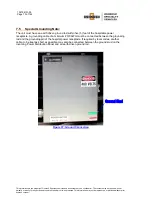
Страница 70: ...or express consent 7 5 Special Grounding Note The unit must have an earth driven ground rod within five 5 feet of the hospitable power receptacle A grounding cable of a minimum 3 0 AWG must be connect...

Страница 71: ...o shore power the red 480V AC FAULT may illuminate and flicker If the red 480V AC FAULT stays illuminated reconnect to generator power and call a certified electrician before attempting to reconnect t...

Страница 72: ...ion binder for the product manual the Oshkosh Specialty Vehicles VOL I Service Operation Manual binder for a list of local service representatives Figure 38 Generator 120V AC Power Outlet An additiona...

Страница 73: ...r at all times Generator power is used while the mobile unit is being transported and shore power can be used while the mobile unit is in the parked position When turning the selector from one positio...

Страница 74: ...of Oshkosh Specialty Vehicles and is considered to be confidential The contents may not be used either partially or wholly for any purpose inconsistent with which it was produced This information may...

Страница 75: ...ions regarding temperature and humidity All aspects of the HVAC system such as damper settings venting component set points and sensor placement are adjusted for optimum operation Under no circumstanc...

Страница 76: ...bulbs located in the return air stream control the heaters and sensors in the supply ducts control the A C unit Chilled liquid is supplied to the magnet shield cooler compressor through a common circ...

Страница 77: ...ration of the HVAC system at all times refer to Section 14 General Maintenance and Section 15 Specific Maintenance 9 2 System Specifications and Descriptions The HVAC system utilizes forced air The HV...

Страница 78: ...should the settings of the humidifier be altered In order for the humidifier to function properly the water tank level must be maintained at all times Figure 42 Humidifier Tank Exterior Fill The exte...

Страница 79: ...t the interior of the mobile unit If for any reason the airflow is disrupted the humidifier will shut down When the sensor detects that relative humidity has been reached a signal is sent to the humid...

Страница 80: ...etting 9 8 Humidity Settings All settings for the humidity system are preset at the factory Under no circumstances should factory presets be altered The humidity low set point is 30 RH relative humidi...

Страница 81: ...Northern Air Service information provided in the Oshkosh Specialty Vehicles VOL II Vendor Information binder for the product manual The condensing coils are directed up to prevent damage during trans...

Страница 82: ...cryogen compressor and the compartment heater are located in the right side compartment This heater provides 1 5KW of heat The compartment heater will activate when the temperature drops below 40 F an...

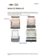
Страница 83: ...sclosed without prior express consent Section 10 Platform Lift The mobile unit contains a Platform Lift that is used to move personnel and equipment from the ground level to the floor level of the mob...

Страница 84: ...is connected to the trailer These devices are used to notify the operator of the Platform Lift status during transport CR also removes power from the lift hydraulic system when all three micro switche...

Страница 85: ...he roll door should not be opened unless this light is on This light is designed to prevent the operator or other personnel from inadvertently stepping out of the roll door when the Platform Lift is n...

Страница 86: ...refer to the Oshkosh Specialty Vehicles VOL II Vendor Information binder for the product manual the Oshkosh Specialty Vehicles VOL I Service Operation Manual binder for a list of local service repres...

Страница 87: ...the Transport Lift Restraining Cable 6 Remove the transport pins 7 Using the remote raise the lift high enough to clear the cradles 8 Carefully pull down the platform until it is parallel with the gr...

Страница 88: ...of Oshkosh Specialty Vehicles and is considered to be confidential The contents may not be used either partially or wholly for any purpose inconsistent with which it was produced This information may...

Страница 89: ...larm Keypad 11 1 Operation The alarm is operated via a keypad located by the staff door When entering the mobile unit the operator keys in a code to deactivate the alarm When leaving the mobile unit t...

Страница 90: ...of Oshkosh Specialty Vehicles and is considered to be confidential The contents may not be used either partially or wholly for any purpose inconsistent with which it was produced This information may...

Страница 91: ...g legs installed on this mobile unit are only for the purpose of parking and stabilizing the mobile unit For additional information please refer to the OEM supplied literature The literature can be fo...

Страница 92: ...he medical system and the mobile unit itself RAISE to install Stands When the switch is in the ON position and the lever is in the UP position the rear air suspension will inflate and raise the rear o...

Страница 93: ...terior lighting Explanations are listed below concerning the lighting systems installed on this mobile unit 13 1 Emergency Lighting In the event that the main AC power fails three dual beam emergency...

Страница 94: ...obile unit The exterior lighting system can be divided as follows For additional information of the warning lights please refer to Appendix B Troubleshooting Underbody Compartment Lighting Located ins...

Страница 95: ...s produced This information may not be reproduced or disclosed without prior express consent Service Lighting Figure 53 Drop Light A cord o matic drop light with a 50 0 cable is supplied with the mobi...

Страница 96: ...provided lighting is insufficient The switch for this light is located inside of the mobile unit on the raceway next to the staff door Figure 54 Staff Door Lighting Marker Running Lights When the mobi...

Страница 97: ...uipment Room are located just inside the Staff Entry door to that leads into Control Room Recessed light fixtures are located in the ceiling panels and have been strategically placed for effective ill...

Страница 98: ...stems are as follows Two switches located next to the Scan Room door controls the halogen lighting located in the ceiling panels The center mounted patient prep light is located directly above the pat...

Страница 99: ...mes during transit or while in the parked position A description of each of the warning lights and their location can be found below If any of the warning lights are illuminated please refer to Append...

Страница 100: ...vice Operation Manual binder for a list of local service representatives or contact Oshkosh Specialty Vehicles for service Refer to Appendix B Troubleshooting for more information Transport Warning St...

Страница 101: ...s and can serve as safety goggles Be certain to disconnect the power before working on any of the electrical systems When servicing the unit be certain that a first aid kit and fire extinguisher are w...

Страница 102: ...levels in the generator and refill if necessary 5 Check the electrolyte levels in the DC batteries and fill if necessary using only distilled water 6 Check all running lights marker lights brake light...

Страница 103: ...on of the smoke detectors and vacuum internally 5 Check the fire extinguisher gauges for safe charges 6 Inspect the power cables for any damage 7 Check the cable tie downs 8 Check for cut damaged or l...

Страница 104: ...Maintenance Checklist must be completed each quarter Oshkosh Specialty Vehicles has included in the Oshkosh Specialty Vehicles VOL I Service Operation Manual binder a Preventive Maintenance Checklist...

Страница 105: ...fan motors if applicable Inspect covers fasteners Verify compressor amp draw Verify condensate pans drains Verify Condenser motor operation Chiller 3M 6M 9M 12M Comments Inspect electrical contactors...

Страница 106: ...door hinges stops latches for proper operation Inspect Slide outs for operation Inspect Slide out compressor Empty compressor drain and verify Y strainer is cleaned out Check Fire system Last Inspect...

Страница 107: ...g mounting bolts Inspect muffler brackets Verify battery charging voltage Load test battery clean terminals Verify voltage hertz output Record hours run since last P M _______ Recorded Generator Hours...

Страница 108: ...of Oshkosh Specialty Vehicles and is considered to be confidential The contents may not be used either partially or wholly for any purpose inconsistent with which it was produced This information may...

Страница 109: ...to disconnect the power before working on any of the electrical systems The HVAC system is critical to the operation and life of the equipment The medical equipment operates within strict limits regar...

Страница 110: ...ater tank fill valve and the other end to the shore supply 4 Turn on the water source to begin filling the tank 5 After the water tank is full turn off the water source 6 Detach the hose at both ends...

Страница 111: ...ompanying manual for the landing gear system 1 Extend the landing legs and coat lightly with clean grease 2 Grease the alemite fittings and check the valve on each leg Use NGLI lithium grease with a g...

Страница 112: ...of Oshkosh Specialty Vehicles and is considered to be confidential The contents may not be used either partially or wholly for any purpose inconsistent with which it was produced This information may...

Страница 113: ...tion via shore power Always inspect the power cable connectors and fasteners prior to usage If during inspection it is suspected that either internal or external damage has occurred have a certified e...

Страница 114: ...in invalidating the Siemens Magnet Technology warranty Disobeying posted speed limits driving dangerously driving while under the influence of alcohol or drugs driving without a valid operators licens...

Страница 115: ...s needed Use the front landing stabilizing legs as well as the rear suspension as necessary Set the trailer parking brake 7 Disconnect the tractor air and electrical lines 8 Lower the auxiliary suppor...

Страница 116: ...mbly 9 Move the shore power disconnect to the OFF position and disconnect the power cable 10 Disconnect the water supply and the wastewater connections 11 Disconnect phone and data lines 12 Raise the...

Страница 117: ...ore power must be connected If the mobile unit is being transported then the vehicle must be stopped and the following items checked Please refer to the product manual located in Volume II of the lite...

Страница 118: ...lso located in the volume is a list of local service representatives For any additional information please contact Oshkosh Specialty Vehicles Humidity is out of specifications The humidity setting for...

Страница 119: ...nditioner filters After this has been done check for any changes to the humidity levels 3 Check to see if the A C disconnect is in the OFF position Turn the A C disconnect to the ON position 4 Check t...

Страница 120: ...sconnect is in the OFF position Turn the A C disconnect to the ON position The temperature inside of the mobile unit is too warm 4 The Temperature Control settings are correct Verify that the Temperat...

Страница 121: ...ctory specifications Be certain that the HVAC system is operational at all times There are two set points for the HVAC system These points are set at the factory and should not be changed under any ci...

Страница 122: ...of Oshkosh Specialty Vehicles and is considered to be confidential The contents may not be used either partially or wholly for any purpose inconsistent with which it was produced This information may...

Страница 123: ...tion Checklist Category 1 Visual Checks Check for the most common occurrences 1 Has the Start button been depressed 2 Is the mobile unit on shore power 3 Is the CB5 circuit breaker in the 480V AC elec...

Страница 124: ...of Oshkosh Specialty Vehicles and is considered to be confidential The contents may not be used either partially or wholly for any purpose inconsistent with which it was produced This information may...

Страница 125: ...Hazardous Energy Type of Hazardous Energy When is it Necessary to Lock Out Electrical 480V AC When servicing main electrical power line Electrical 120V AC room circuits When servicing or performing i...

Страница 126: ...rcuits Lock and tag with a Universal Wall Switch Lockout Universal Circuit Breaker Lockout Roll Door Electrical 120V AC Circuit Breaker Service Switch CB in 208 V AC Panel Switch in overhead panel abo...

Страница 127: ...teries or replacing the sensor as described in the users manuals the unit must be sent back to the factory for repair or replacement See Return Authorization for Service for instructions on obtaining...

Страница 128: ...nstrument refer to the procedures below The MX300 I should be calibrated before each use and every 8 hours to maintain accuracy Whenever new batteries are installed or removed for any reason the oxyge...

Страница 129: ...Never calibrate the unit in humidified gas as water vapor makes the oxygen concentration appear lower than it really is Do not adjust the calibration settings in air after the 100 calibration as this...

Страница 130: ...m temperature the resulting gas mixture will contain only 77 5 oxygen Your portable oxygen monitor accurately measures decreases in the oxygen concentration due to the dilution effects of moisture add...

Страница 131: ...ressure of oxygen Assuming that the sensor is fast enough to track this pressure pulse an un pressurized reading of 50 oxygen will increase to 55 3 if the sensor is subjected to a pressure cycle of 10...

Страница 132: ...lies refer to the following guidelines in Table 1 Table 1 Troubleshooting Symptom Why What To Do New sensor responds slow or drifts If the sensor is new and was just removed from its sealed bag it ma...

Страница 133: ...pment and two way radios A Check sensor cable connections and make sure they are completely inserted into the mating connector and the capture nut is firmly in place B Expose the sensor in 100 02 and...

Страница 134: ...on below Several conditions can activate the watch dog Dropping the unit poor battery connections and radio frequency interference are the most common causes See the watch dog section for additional i...

Страница 135: ...For example the error code 6 and 7 are followed by another digit listed as N in Table 2 The error code 65 would indicate that a key is stuck and this key is the Silence key In addition to supplying v...

Страница 136: ...t on the board is not feasible It requires specialized test equipment and probes not generally available to the public Under most circumstances a replacement of the entire PC Board is recommended The...

Страница 137: ...rvice beyond sensor and battery replacement the instrument must be returned to the factory A return merchandise authorization RMA number must be obtained from Teledyne Analytical Instruments prior to...

Страница 138: ...of Oshkosh Specialty Vehicles and is considered to be confidential The contents may not be used either partially or wholly for any purpose inconsistent with which it was produced This information may...

Страница 139: ...Thermostats Verify heat strip operation Inspect clean evaporator coil Clean inspect condenser coils Inspect electrical contactors Verify refrigerant pressures Inspect refrigeration piping abrasion Lu...

Страница 140: ...ls Inspect roll door key way Inspect awning Inspect bay door shocks hardware Verify bay light operation Inspect clean and RF door gasket Verify RF door operation Verify RF door lock and the handle ope...

Страница 141: ...Verify radiator coolant level Verify coolant freeze point pH Verify block heater operation Inspect housing mounting bolts Inspect muffler brackets Verify battery charging voltage Load test battery cl...

Страница 142: ...d is considered to be confidential The contents may not be used either partially or wholly for any purpose inconsistent with which it was produced This information may not be reproduced or disclosed w...

Отзывы: