background image

UNIT

BLACK (BLK)

SENSOR

 SWITCH

SWITCH BOX

POWER SUPPLY

120V AC

GROUND (GRD)

BROWN (BRN)

WHITE (WHT)

FAN 

RECEPTACLE

SENSOR

RECEPTACLE

       FAN

SWITCH

FAN

Run 120 V AC house wiring to the location of the fan. Use only UL-approved connectors (not included) to attach the house wiring to the 

wiring plate. Refer to the wiring diagram, and connect the wires as shown.

ASSEMBLY INSTRUCTIONS

CONNECT ELECTRICAL WIRING

3

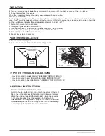
2. MOUNT WITH HANGER BARS

    Insret the hanger bars into the slots in the housing. Place the fan 

    housing between the joists, make sure the bottom of the housing

    is even with the finished ceiling. Extend the hanger hars to the 

    joist. Use screws to secure the hanger bars to the

    ceiling joists.  

DUCT

3. ATTACH DAMPER/DUCT CONNECTOR

   Snap the damper/duct connector onto the fan housing. The 

   connector must be flush with the top of the housing, and the 

   damper flap should fall closed.

4. INSTALL ROUND DUCTWOTK

    Connect the round ductwork (not included) to the damper/duct connector, 

    and run the ductwork to a roof or wall cap (not included). Using tape (not 

    included), secure all the ductwork connections so that they are air tight.

D

For OD-5006HS OD-8011HS

For OD-5006 OD-8011 

UNIT

BLACK (BLK)

SWITCH BOX

       FAN

SWITCH

POWER SUPPLY

120V AC

GROUND (GRD)

WHITE (WHT)

WIRE 

PANEL 

WIRE 

PANEL 

FAN 

RECEPTACLE

FAN

Содержание OD-5006

Страница 1: ...ion in ceilings up to a 12 12 pitch 45 degree angle Duct connector must point up DO NOT MOUNT THIS PRODUCT IN A WALL 3 To avoid motor bearing damage and noisy and or unbalanced impellers keep drywall...

Страница 2: ...operation by turning on the shower or other humidity source until the fan turns on 5 Repeat above steps if necessary When the temperature changes humidity sensor values will have deviation TIMER ADJU...

Страница 3: ...m of the housing is even with the finished ceiling Extend the hanger hars to the joist Use screws to secure the hanger bars to the ceiling joists DUCT 3 ATTACH DAMPER DUCT CONNECTOR Snap the damper du...

Страница 4: ...ssembly Grille Spring Blower Assembly includes part 3 6 7 Replacement installation Remove the screw on motor plate part 3 then take out the motor plate part 3 from the housing part 9 by pushing down t...

Страница 5: ...OD 5006 OD 5006HS OD 8011 OD 8011HS Four Model OD 5006HS OD 8011HS VENTILATEUR AVERTISSEMENT PRECAUTION L ENTRETIEN ET LE NETTOYAGE FONCTIONNEMENT 5...

Страница 6: ...ez l chement le bo tier la solive en ins rant des vis bois dans les encoches en trou de serrure des languettes de montage R glez la position du bo tier de fa on ce qu il soit au m me niveau que le pla...

Страница 7: ...UR L ASSEMBLAGE 2 INSTALLATION AVEC BARRES DE SUSPENSION Ins rez les barres de suspension dans les fentes du bo tier Placez le bo tier du ventilateur entre les solives de fa on ce que le bord inf rieu...

Страница 8: ...t de pi ces Enlevez la vis puis retirez la plaque du moteur pi ce 3 du bo tier en poussant la nervure vers le bas tout en tirant sur le c t du bo tier pi ce 9 Remplacez les pi ces d fectueuses PI CE N...

Отзывы: