


IG-175-EN version 02; 17/06/2016
18
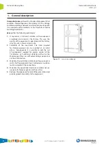
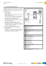
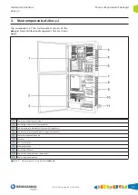
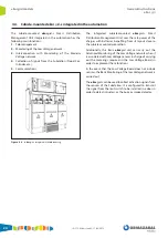
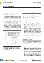
Main components of ekor.gid
General Instructions
ekor.gid
c. 48 V
DC
output at protective earth potential for
charging the batteries. (The batteries are housed in
the Communications compartment).
4. Input / output insulation (in the power supply): The
insulation must be 10 kV / 50 Hz / 60 s between the
power supply parts that are at Low Voltage potential
(48 V
DC
input and output in Low Voltage) and the
components at protective earth potential.
5. Short-circuitable output by means of a resettable fuse.
6. Operating temperature range: - 10 to + 60 ºC in
accordance with standard NI 70.02.01
7. Ventilation by natural convection without mechanical
components.
8. Alarms:
a. Alarms for incorrect operation of the equipment
and the batteries.
b. Alarm for Loss of Alternating Voltage.
Required functionality:
1. Upon loss of Low Voltage, there cannot be zero voltage;
instead, it should switch to being supplied directly from
the batteries.
2. Batteries test.
The 10 kV of insulation at the power source prevents having
to install an additional insulation transformer to protect the
units housed inside the Communications Compartment,
which affects the reliability of the assembly.
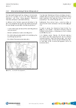
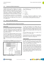
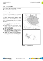
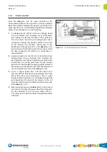
3.4.6. Ethernet
The Ethernet gateway is a component integrated inside the
ekor.gid Low Voltage Compartment and implements the
following functions:
1. Radio Receiver for Advanced Monitoring of the Low
Voltage network
2. MODBUS master
3. 10 kV insulation
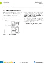
Advanced monitoring of the Low Voltage network
1. Radio Receivers
The radio receivers implement the following
functionality:
- Current metering per each one of the Low Voltage
board (or fuse) outputs.
- Blown fuse detection in each Low Voltage line.
- Possibility of developing algorithms for identifying
the Low Voltage connectivity.
- Possibility of fuse temperature detection.
Two radio receivers are installed inside the ekor.gid unit:
one for each Low Voltage board that may be monitored.
Each Radio Receiver can monitor up to 36 radio transmitter
positions or Low Voltage fuses.
Additionally, the Radio Receiver stores information of
the transmitter / receiver configuration. This information
corresponds to:
1. Identifier of each one of the sensors (transmitter) that
are added in Low Voltage (from 1 to 36).
2. Version of the firmware available in the sensor.
3. Sensor serial number.
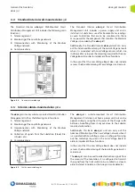
MODBUS master
The Ethernet Gateway also carries out the functions
corresponding to a master in a Modbus communications
bus.
This component is in charge of managing the
communications with the Radio Receiver and the Low
Voltage Monitor, and facilitating all the information of this
bus to the communication components via Ethernet.
10 kV insulation
The Ethernet Gateway, which is at Low Voltage potential,
is connected directly to the communication components,
which are at protective earth potential. Therefore, this
component includes an additional 10 kV / 50 Hz / 60 s
insulation.


