background image

IG-284-EN version 03; 06/05/2020

69

General Instructions

cgm

.800: Medium-voltage switchgear with integrated insulation in SF

6

 gas 

up to 36 kV in accordance with IEC Standard with rated current up to 800 A

Environmental information

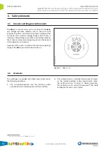
9.  Environmental information

[16]

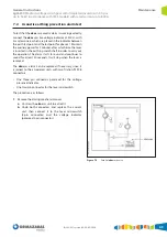
 This information is given on a label on the equipment itself.

cgm

.800 cubicles are defined as a pressure-sealed system, 

according to IEC 62271-1, which contains hexafluoride 

(SF

6

).

[16]

SF

6

 contained in the 

cgm

.800 switchgear systems complies 

with the quality requirements of standard IEC 60376.

SF

6

 is included in the Kyoto Protocol list of greenhouse 

gases. SF

6

 has a GWP (Global Warming Potential) of 


22,200 units. (TAR, IPCC 2001).

At the end of the product's life, the SF

6

 contained in it 

must be recovered for processing and recycling, to prevent 

it being released into the atmosphere. Extracting and 

handling of SF

6

 must be carried out by qualified personnel, 

using a sealed piercing system. 

For the usage and handling of the SF

6

, the indications listed 

in IEC 62271-303 must be followed.

Management and treatment of the rest of materials must 

be carried out in accordance with the country’s current 

legislation.

Содержание velatia cgm.800

Страница 1: ...B cgm 800 Medium voltage switchgear with integrated insulation in SF6 gas up to 36 kV in accordance with IEC Standard with rated current up to 800 A General Instructions IG 284 EN version 03 06 05 202...

Страница 2: ...ectrical installations Personnel must be fully familiar with the instructions and warnings contained in this manual and in other recommendations of a more general nature which are applicable to the si...

Страница 3: ...ve voltage indicator 35 5 3 Phase concordance check 36 5 4 Feeder function 37 5 4 1 Mimic diagram 37 5 4 2 Actuating levers 37 5 4 3 Opening operation from earthing position 38 5 4 4 Switch closing op...

Страница 4: ...Function cgm 800 l Feeder cgm 800 p Protection with fuses cgm 800 v Vacuum circuit breaker cgm 800 rc Cable rise cgm 800 ma Metering and auxiliary services Table 1 1 cgm 800 system models 1 2 Standard...

Страница 5: ...on female bushings 2 Driving mechanism area 2 1 Name plate 2 2 Operating sequence plate 2 3 Actuating shafts see mimic diagram of each model 2 4 ekor vpis ekor ivds live voltage detector 2 5 ekor sas...

Страница 6: ...medium voltage circuit is displayed on the cover of this compartment The mimic diagram includes all the position indicators for the driving elements The cgm 800 system has in line with the cubicle mod...

Страница 7: ...nal reduced plus surge arrester reduced with space for the corresponding incoming power cables Cable ties for the power cables Earthing bars As an option Two symmetric terminals or symmetric terminal...

Страница 8: ...ing impulse withstand voltage kV Ud Power frequency withstand voltage kV fr Equipment rated frequency Hz Ir Equipment rated current A Instructions Manual General Instructions Manual IG for the system...

Страница 9: ...voltage 125 145 170 195 Internal arc in tank Front accessibility 20 25 kA 0 5 s Front and side accessibility 20 25 kA 1 s Front side and rear accessibility 20 25 kA 1 s Internal arc classification acc...

Страница 10: ...a mm Depth f mm Height h mm Bushings height g mm Cable fastening height l mm Weight kg l 418 850 1 1400 1 697 234 147 1745 1042 580 162 p 480 1010 1400 1 180 128 215 1745 230 v 600 2 850 1400 1 350 20...

Страница 11: ...measured over a 24 hour period 2 2 kPa Maximum mean vapour pressure measured over a 1 month period 1 8 kPa Maximum height above sea level 2000 m Solar radiation Negligible Ambient air pollution dust s...

Страница 12: ...damage the equipment 2 1 Lifting means The switchgear must always be kept upright directly on the ground or on a pallet depending on the type of handling involved To handle assemblies of up to four cg...

Страница 13: ...elp get over the cable trench 4 To handle the series of five functional cgm 800 units coupled modules use lifting systems slings lifting beam etc with a pull angle greater than 65 and less than 115 in...

Страница 14: ...e both in transport and in storage must not exceed 2000 m 5 The environmental air must not have any significant contamination from dust smoke corrosive and or inflammable gases vapours or salt 6 The s...

Страница 15: ...he cellophane 3 Detach the white polystyrene corner pieces 4 Unscrew the fixings between the base and the pallet 5 Remove the pallet handling the cubicle as indicated in section 2 1 6 Unpack the acces...

Страница 16: ...The minimum distances to the walls and roof which must be maintained in the facility are as follows Figure 4 3 Minimum installation distances Minimum distances mm Side wall a 100 Ceiling b Height 1400...

Страница 17: ...1 Cubicles with internal arc in tank up to 20 kA 7 0 5 s Feeder and cable rise function The dimensions of the trench depend on the minimum radius of curvature of the cables used Front and rear cable...

Страница 18: ...utput D2 Figure 4 5 Dimensions mm of the cable trench for cgm 800 p Trench necessary for the fuse protection function Cable data Approximate radius of curvature mm Minimum depth Cable insulation Cable...

Страница 19: ...v with AV RAV driving mechanism Trench necessary for the circuit breaker with AV RAV driving mechanism function Cable data Approximate radius of curvature mm Minimum depth Cable insulation Cable type...

Страница 20: ...y for the feeder and cable rise function Cable data Approximate radius of curvature mm Minimum depth Cable insulation Cable type Cable section mm2 Cable diameter mm D1 mm D2 mm Height 1400 mm Dry insu...

Страница 21: ...of the cable trench for cgm 800 ma Trench necessary for the metering function and auxiliary services Cable insulation Cable type Cable section mm2 Cable diameter mm Approximate radius of curvature mm...

Страница 22: ...ecessary for the fuse protection function Cable data Approximate radius of curvature mm Minimum depth Cable insulation Cable type Cable section mm2 Cable diameter mm D1 mm D2 mm Height 1400 mm Dry ins...

Страница 23: ...data Approximate radius of curvature mm Minimum depth Cable insulation Cable type Cable section mm2 Cable diameter mm D1 mm D2 mm Height 1400 mm Dry insulation Single Core 150 41 555 750 750 185 43 59...

Страница 24: ...hich may make it difficult to connect the cubicles to one another The cubicles can be fastened to the floor in two ways 4 5 1 Fastening to the floor on profile If the floor of the facility is not suff...

Страница 25: ...thing position Except in circuit breaker functions which will be in isolating position 2 Removethecablecompartmentcover usingthecentral handle on the cover to pull it up and forward Figure 4 12 Removi...

Страница 26: ...with IEC Standard with rated current up to 800 A Figure 4 13 Detail of anchor points in cgm 800 l p v cubicles measuring 1745 mm high Figure 4 14 Detail of anchor points in cgm 800 l p v cubicles meas...

Страница 27: ...ation In order to anchor this type of cubicles properly use the six points indicated in the figure below For further information contact Ormazabal Figure 4 17 Anchor points for earthquake resistant eq...

Страница 28: ...is supplied with the materials kit used for connecting cubicles 4 7 Earthing the switchgear When connecting the general earth collector follow the figure below Figure 4 21 Equipment earthing 1 Bolt th...

Страница 29: ...touch live connectors not even screened connectors Screening does not constitute a protection against direct contact When the equipment is in service and a reserve cubicle is left with voltage in the...

Страница 30: ...d with rated current up to 800 A 4 8 1 Horizontal front connection 1 Close the earthing switch 2 Remove the cover to access the cable compartment Figure 4 22 Cable compartment detail 3 Connect the ter...

Страница 31: ...th integrated insulation in SF6 gas up to 36 kV in accordance with IEC Standard with rated current up to 800 A Installation 4 Connect the terminal earth braids if applicable and the cable screens Figu...

Страница 32: ...on 1400 mm high The cable support in fuse protection functions measuring 1400 high is supplied secured to the base with two M8 bolts and nuts as shown in Figure 4 25 Figure 4 25 Cable support in trans...

Страница 33: ...andard with rated current up to 800 A Installation 2 Turn the cable support and position it as shown in Figure 4 27 Figure 4 27 Cable support positioning 3 Position the four M8 bolts with their nuts a...

Страница 34: ...ion when voltage is present we recommend checking the SF6 gas pressure using the pressure gauge 5 1 Checking the gas pressure Each gas tank has a pressure gauge for checking the gas pressure which can...

Страница 35: ...ide a clear visual indication for the user without needing an auxiliary power supply for operation For each of the three phases the presence of voltage is indicated by intermittent flashing of the ind...

Страница 36: ...feeder cubicles Firstly connect the red cables of the ekor spc unit to the corresponding phase test points in the voltage indication units 14 and the black cable to the earth test point This operation...

Страница 37: ...alarm b Pressure gauge window c Live voltage indicator ekor vpis or ekor ivds d Operation area GREY for switch disconnector YELLOW for earthing switch e Status indicators BLACK for switch disconnector...

Страница 38: ...from earthing position 1 Move the actuating shaft access handle in the yellow zone to its bottom position 2 Opening operation a Manual operation Insert the lever in the earthing switch driving shaft m...

Страница 39: ...open position 1 Move the actuating shaft access handle in the grey zone to its bottom position 2 Connecting operation a Manual operation B driving mechanism Inserttheleverintheswitchaccess greyarea m...

Страница 40: ...position 1 Move the actuating shaft access handle in the grey zone to its bottom position 2 Opening operation a Manual operation B driving mechanism Insert the lever in the switch access grey area mov...

Страница 41: ...from the open position 1 Move the actuating shaft access handle in the yellow zone to its bottom position 2 Earthing operation a Manual operation Insert the lever in the earthing switch actuating sha...

Страница 42: ...cover has been put back The cable test can only be carried out in cgm 800 feeder functions which include B BM B2M driving mechanisms with this characteristic Please check with Ormazabal 1 Follow the...

Страница 43: ...ekor ivds d Operation area YELLOW for earthing switch GREY for switch disconnector e Status indicators BLACK for switch disconnector RED for earthing switch f Actuating shaft access handles g Manual t...

Страница 44: ...ove the driving shaft access handle to its lower position 2 Opening operation a Manual operation Insert the lever in the earthing switch driving shaft move the drive arm to the end and press inwards o...

Страница 45: ...peration Insert the lever in the switch disconnector driving shaft move the drive arm to the end and press inwards on the head of the lever with one hand and turn clockwise with the other hand In the...

Страница 46: ...ce with IEC Standard with rated current up to 800 A 5 5 5 Opening operation from switch disconnector closed position 1 The switch can be opened manually using the push button on the front of the cubic...

Страница 47: ...ove the driving shaft access handle to its lower position 2 Earthing operation a Manual operation Insert the lever in the earthing switch driving shaft move the drive arm to the end and press inwards...

Страница 48: ...this is indicated by the red position indicator b located on the front of the driving mechanism compartment As an option an auxiliary blown fuse indication for any of the three fuses is also available...

Страница 49: ...s unhooked and then pull sharply outwards to open the fuse holder Figure 5 30 Fuse holder opening 4 Remove the fuse holder carriage by pulling it outward Figure 5 31 Removing the fuse holder carriage...

Страница 50: ...t the fuse holder carriage in its compartment by pulling it inward Before inserting the fuse holder carriage in the fuse protection cubicle ensure that both the carriage as well as the inside of the f...

Страница 51: ...the cover and check that all the strikers have been reset Figure 5 36 Fuse holder closure 9 Position the fuse and cable compartment access cover a by pushing it downward and ensuring it is locked on t...

Страница 52: ...measuring 292 mm long Fuses measuring 537 mm long For fuses measuring 442 mm long check with Ormazabal For cubicles with associated fuses Table 5 1 Fuse calibres for 24 kV cubicles Ur kV Transformer...

Страница 53: ...b Pressure gauge window c Live voltage indicator ekor vpis or ekor ivds d Operation area YELLOW for earthing switch GREY for switch disconnector e ekor rpg ekor rpa protection unit f Status indicators...

Страница 54: ...drive and spring charge levers to be used to drive the switch disconnector earthing switch of the circuit breaker function with AV RAV driving mechanisms are Figure 5 39 Switch disconnector actuating...

Страница 55: ...p to 800 A Recommended sequence of operations 2 Opening operation a Manual operation Insert the lever in the earthing driving shaft move the driving arm to the end and turn anti clockwise b Motorised...

Страница 56: ...urrent up to 800 A 5 7 4 Closing operation from isolating position Initial conditions Earthing switch open circuit breaker closed and springs charged 1 Open the circuit breaker by pressing the 0 butto...

Страница 57: ...rn details 3 Remove the lever The handle returns to its original position 4 Charge the springs by introducing the spring charging lever in the spring charge shaft k and turn until the charged spring i...

Страница 58: ...ent up to 800 A 5 7 5 Opening operation from closed position Initial conditions Circuit breaker closed earthing switch open and springs charged 1 Open the circuit breaker by pressing the 0 opening but...

Страница 59: ...itch disconnector opening operation a Manual operation Insert the lever in the disconnector driving shaft move the driving arm to the end and turn anti clockwise 90 b Motorised operation BR AM BRA 2M...

Страница 60: ...urrent up to 800 A 5 7 6 Earthing operation from open position Initialconditions Circuitbreakeropen earthingswitch open and springs charged 1 Close the circuit breaker by pressing the l close button a...

Страница 61: ...e lever in the earthing switch driving shaft move the driving arm to the end and turn clockwise 90 b Motorised operation B2M driving mechanism Activate the corresponding operation command Figure 5 54...

Страница 62: ...the lever is inserted in the earthing switch shaft A sound then indicates that a short circuit or zero voltage may occur in the network if the operation is carried out Operation of the unit is assure...

Страница 63: ...terlocking for both the switch disconnector in closed or open positions and for the earthing switch in closed or open positions Padlocks with ring diameters of between 8 and 11 mm can be used Figure 6...

Страница 64: ...e conditions in excess of those defined as normal service conditions IEC 62271 1 must carry out the regular preventive maintenance tasks required Check with Ormazabal for the environmental conditions...

Страница 65: ...e the lever is inserted in the earthing switch shaft in order to carry out the operation The alarm starts to sound and continues to sound for at least 30 seconds It will stop when the lever is removed...

Страница 66: ...nisms and other elements outside the gas tank may require preventive maintenance the frequency of this maintenance depends on the existing environmental conditions harsh environments dust extreme temp...

Страница 67: ...rthing grounding Switch X X 1 X Circuit breaker X Side connection female bushings X X X Fuse holder compartment X Front connection bushings X X X Side connection bushings O O O Pressure gauge X X X Te...

Страница 68: ...N O O O Circuit breaker CLOSED O Earth connection CLOSED OPEN O O O Opening the access cover O Others l p v rc Control box O O O Auxiliary profiles for fastening to the floor O O O O Operating sequenc...

Страница 69: ...systems complies with the quality requirements of standard IEC 60376 SF6 is included in the Kyoto Protocol list of greenhouse gases SF6 has a GWP Global Warming Potential of 22 200 units TAR IPCC 200...

Страница 70: ...G 284 EN version 03 06 05 2020 70 Notes General Instructions cgm 800 Medium voltage switchgear with integrated insulation in SF6 gas up to 36 kV in accordance with IEC Standard with rated current up t...

Страница 71: ......

Страница 72: ...Subject to change without prior notice For further information please ask Ormazabal Ormazabal y C a IGORRE Spain www ormazabal com...

Отзывы: