


8
IM0973112 A 03
IM0973112 A 03
9
Set preset is also used for some special function by using a special Preset ID.
Pan/Tilt unit:
Preset ID 0x56 Start wipe/wash cycle, this blocks white hot LUT selection in pan/tilt/TIC combination.
Autofocus camera:
Preset ID 0x58 and 0x15 will switch the IR block filter into the optical path.
Preset ID 0x59 and 0x16 will switch the IR block filter out of the optical path.
TIC camera:
Preset ID 0x55 Switch to the Black hot color LUT.
Preset ID 0x56 Switch to the White hot color LUT (not available when combined with pan/tilt unit).
Preset ID 0x57 Switch to the Ice&fire color LUT.
Preset ID 0x58 and 0x15 Switch to the Rainbow color LUT.
Preset ID 0x59 and 0x16 Will force a flat field calibration cycle.
Clear Preset:
Byte Byte 2 Byte 3 Byte 4 Byte 5 Byte 6 Byte 7
Sync addr. 0x00 0x05 0x00 Preset chksm
0xff
ID
Preset ID valid range = 0-5.
Go To Preset (not for TIC camera):
Byte 1 Byte 2 Byte 3 Byte 4 Byte 5 Byte 6 Byte 7
Sync addr. 0x00 0x07 0x00 Preset chksm
0xff
ID
Preset ID valid range = 0-5.
Set Zoom Speed:
Byte 1 Byte 2 Byte 3 Byte 4 Byte 5 Byte 6 Byte 7
Sync addr. 0x00 0x25 0x00 Zoom chksm
0xff
Speed
Remarks: Zoom speed valid values 0-3.
Set Focus Speed:
Byte 1 Byte 2 Byte 3 Byte 4 Byte 5 Byte 6 Byte 7
Sync addr. 0x00 0x27 0x00 Focus chksm
0xff Speed
Remarks: Focus speed valid values 0-3.
Auto-focus auto/on/off:
Byte 1 Byte 2 Byte 3 Byte 4 Byte 5 Byte 6 Byte 7
Sync addr. 0x00 0x2B 0x00 Focus chksm
0xff
ctrl
Remarks: Focus ctrl 0,1 = Auto, 2 = off.
Backlight compensation on/off:
Byte 1 Byte 2 Byte 3 Byte 4 Byte 5 Byte 6 Byte 7
Sync addr. 0x00 0x31 0x00 BLC chksm
0xff
ctrl
Remarks: BLC ctrl 1 = off, 2 = on.
Installation Manual
Installation Manual
7. Pelco-D commands
Pelco-D protocol as implemented in Orlaco Zoom camera or PTZ unit.
Commands detailed below are accepted, no responses are sent.
Bron:Pelco PTZ protocols, D Protocol, Version 5.0.1 1 april 2008 by Eric Hamilton (C) Pelco.
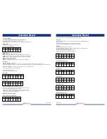
Command format:
All commands are seven (D Protocol)bytes long.
D Protocol Command Format/Names:
Byte 1 Byte 2 Byte 3 Byte 4 Byte 5 Byte 6 Byte 7
Sync addr. cmnd1 cmnd2 data1 data2 chksm
0xff
Bytes D Protocol:
1 sync
: Always 0xFF to indicate the start of a command.
2 addr
: Camera address. Range is 1 ! 255 (0x01 ! 0xFF). 0x01 is for camera #1, etc.
3 cmnd1
: Extension of the basic command. The basic command is in the cmnd2 position.
4 cmnd2
: The basic command. For extended commands, all of these are odd numbers.
5 data1
: Usually is the Pan speed index.
6 data2
: Usually is the Tilt speed index.
7 cksm
: This is the arithmetic sum of all bytes except for the sync byte and itself.
Command Sets
There are two sets/types of commands:
1 “Motion” commands
, i.e. pan, tilt, iris, zoom and focus; are “bit encoded” commands that always have bit 0 in cmnd2 set to 0.
Any number of non-exclusive bits may be set in the cmnd1 and cmnd2 bytes for this format of command, data1 and data2 are pan and tilt speed index.
2 “Non-motion” commands
, i.e. call preset, set pan angular position; are “numerically encoded”.
These commands always have bit 0 in cmnd2 set to a 1.
Implemented “Motion” commands:
cmnd1 and cmnd2 are represented as follows:
Byte 3, cmnd1
Bit 7 Bit 6 Bit 4 Bit 4 Bit 3 Bit 2
Bit 1 Bit 0
0 0 0 0 0 0 0 Focus
Near
Byte 4, cmnd2
Bit 7 Bit 6 Bit 5 Bit 4 Bit 3 Bit 2 Bit 1 Bit 0
Focus Zoom Zoom Down Up
Left Right 0
Far Wide Tele
Data1, Data2 (Pan/Tilt speed), Byte 5,6 contain the speed.
Speed is in the range of `0x00’ to `0x3F’ (high speed) and `0x40’ for “turbo” speed.
Turbo speed is the maximum speed the device can obtain.
A pan speed value of `0x00’ results in very slow motion, not cessation of motion.
To stop pan motion both the Left and Right direction bits must be turned off, set to `0’,
regardless of the value set in the pan speed byte.
Implemented “Non-motion” commands.
Set Preset (TIC has only special presets):
Byte 1 Byte 2 Byte 3 Byte 4 Byte 5 Byte 6 Byte 7
Sync addr. 0x00 0x03 0x00 Preset chksm
0xff
ID
Preset ID valid range = 0-5.