background image

14

accessory installation

Now that the base is assembled and the optical tube assem-
bled and mounted, all that remains is to attach the EZ Finder 
II reflex sight and pop an eyepiece into the focuser.

EZ Finder ii

Using the included dovetail mounting bracket, the EZ Finder II 
will slip neatly into the dovetail base pre-installed on the upper 
tube section adjacent to the focuser. Just slide the dovetail 
mounting bracket into the telescope’s dovetail mounting base 
and tighten the thumbscrew on the base to secure the mount-
ing bracket. Make sure the sight tube of the EZ Finder II is 
forward (closest to front opening of telescope).

operating the EZ Finder ii

Before installing the EZ Finder II on the telescope, you’ll need 
to insert the included 3-volt lithium battery.
1.  Insert a small, flat-blade screwdriver into the notch in the 

battery casing and gently pry it off (

Figure 26).

2.  Slide the CR2032 3V lithium battery under the retaining 

clip with the positive (+) side facing down (touching the 
clip).

3.  Then press the battery casing back on.
Should the battery die, replacement CR2032 batteries are 
available at many stores where small batteries are sold.
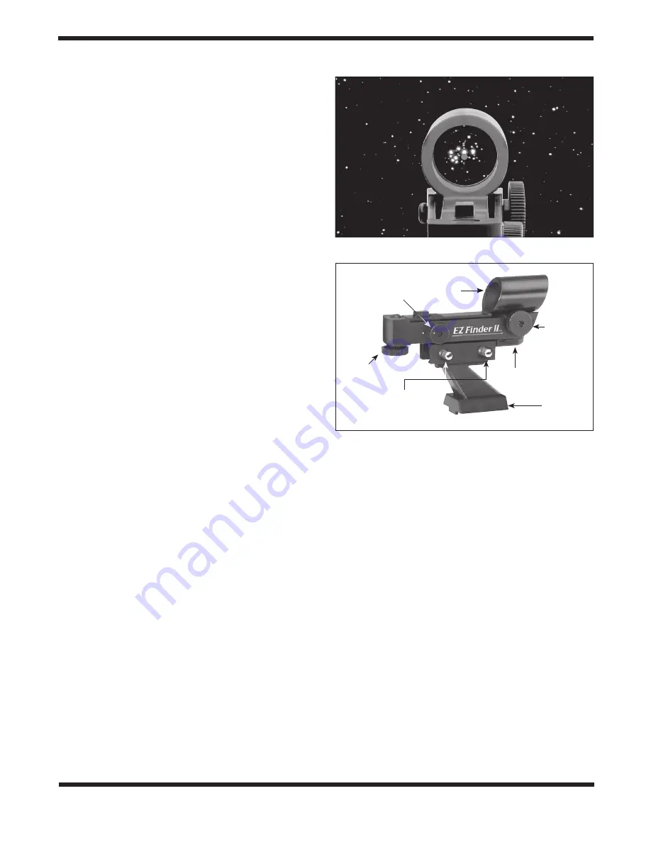
The EZ Finder II works by projecting a tiny red dot (it is not 
a laser beam) onto a lens mounted in the front of the unit. 
When you look through the EZ Finder II, the red dot will 
appear to float in space, helping you to pinpoint your target 
object 

(Figure 25). The red dot is produced by a light-emitting 

diode (LED) near the rear of the sight. Turn the power knob 
(see Figure 26) clockwise until you hear the “click” indicating 
that power has been turned on. Look through the back of the 
reflex sight with both eyes open to see the red dot. Position 
your eye at a comfortable distance from the back of the sight. 
In daylight you may need to cover the front of the sight with 
your hand to be able to see the dot, which is purposefully 
quite dim. The intensity of the dot is adjusted by turning the 
power knob. For best results when stargazing, use the dim-
mest possible setting that allows you to see the dot without 
difficulty. Typically a dimmer setting is used under dark skies 
and a brighter setting is needed under light-polluted skies or 
in daylight.

aligning the EZ Finder ii

When the EZ Finder II is properly aligned with the telescope, 
an object that is centered on the EZ Finder II’s red dot should 
also appear in the center of the field of view of the telescope’s 
eyepiece. Alignment of the EZ Finder II is easiest during day-
light, before observing at night. Aim the telescope at a distant 
object such as a telephone pole or roof chimney and center it 
in the telescope’s eyepiece. The object should be at least 1/4 
mile away. Now, with the EZ Finder II turned on, look though it. 
The object should appear in the field of view. Without moving 
the main telescope, use the EZ Finder II’s azimuth (left/right) 

and altitude (up/down) adjustment knobs (see 

Figure 26

to position the red dot on the object in the eyepiece. When 
the red dot is centered on the distant object, check to make 
sure that the object is still centered in the telescope’s field of 
view. If not, re-center it and adjust the EZ Finder II’s alignment 
again. When the object is centered in the eyepiece and on 
the EZ Finder’s red dot, the EZ Finder II is properly aligned 
with the telescope. Once aligned, the EZ Finder II will usually 
hold its alignment even after being removed and remounted. 
Otherwise, only minimal realignment will be needed. At the 
end of your observing session, be sure to turn the power knob 
to the Off position.

using Eyepieces

The final step in the assembly process is to insert an eye-
piece into the telescope’s focuser. First, take the cover cap 
off the focuser drawtube. To use the 2" DeepView eyepiece, 
loosen the two thumbscrews on the 2" accessory collar (on 
the end of the focuser drawtube) and remove the 1.25" adapt-
er. Then place the 2" eyepiece directly into the 2" accessory 
collar and secure it with the two thumbscrews loosened previ-
ously 

(Figure 27). If you cannot achieve focus, you may need 

to install the included 2" extension adapter on the focuser, 
then insert the eyepiece into it. The other eyepiece and 1.25" 

Figure 26. 

The EZ Finder II reflex sight.

Power knob

Sight 
tube

Altitude 
adjustment 
knob

Thumbscrews

Dovetail 
mounting 
bracket

Battery 
casing

Azimuth 
adjustment 
knob

Figure 25. 

The EZ Finder II superimposes a tiny red dot on the 

sky, showing right where the telescope is aimed.

Содержание SkyQuest xx12g

Страница 1: ...Orion SkyQuest XXg GoTo Truss Tube Dobsonians 10148 XX12g 8964 XX14g 8968 XX16g XX14g Customer Support www OrionTelescopes com contactus Corporate Offices 89 Hangar Way Watsonville CA 95076 USA Provid...

Страница 2: ...rack 2 extension adapter 1 25 eyepiece adapter Top groundplate Bottom groundplate Captive base connecting bolts x12 EZ Finder II 2 DeepView eyepiece 2 Dual speed Crayford focuser Truss poles Lower opt...

Страница 3: ...ips in four boxes with the truss poles and coun terweights contained in a separate box The XX16g is pack aged in five boxes with the base components divided into two separate boxes to keep the weight...

Страница 4: ...232 computer interface cable 1 Hand controller bracket with 2 mounting screws 3 Counterweight mounting bolts XX14g XX16g 1 Cooling accelerator fan with battery holder XX12g only 1 Instruction manual n...

Страница 5: ...s 2 2 lbs each XXX16g only Figure 4 Contents of the truss pole and counterweight box The XX16g contains nine counterweights For the XX12g the truss poles are included in the optical tube box and there...

Страница 6: ...e 2mm 4mm 6mm 3 Plastic feet XX12g only feet are pre installed on XX14g and XX16g 3 Feet wood screws 1 long XX12g only Box 5 Dobsonian Base XX16g only Qty Description 1 Groundplate assembly with azimu...

Страница 7: ...arter holes on the perimeter of the bottom ground plate Figure 6a Insert the screws through the feet and thread them into the predrilled starter holes Figure 6b with a Phillips screwdriver until tight...

Страница 8: ...gure 10 The completed side panel and front panel assembly Figure 12 Find the two pilot holes and attach the hand controller bracket but don t overtighten the screws Figure 11 Place the large opening o...

Страница 9: ...he eyepiece rack over the screw heads and slide it downward until it stops Figure 11 Tighten the screws to secure the rack in place 8 The XXg base includes a bracket that holds the hand controller whe...

Страница 10: ...recommend placing a soft towel on a flat surface and placing the mirror face down on the towel because the aluminized outer edge of the mirror will contact the surface With the XX12g mir ror on the ot...

Страница 11: ...e entire mirror cell assembly should seat onto the tube Now replace the Phillips screws that fas ten the rear end ring to the tube Before assembling the rest of the optical tube you should con sider h...

Страница 12: ...be section as need ed to access the counterweight mounting bolts on the rear cell and thread the counterweights onto each of the three mounting bolts Spin them clockwise until they stop 5 Now attach t...

Страница 13: ...back and firmly tighten the eight clamping knobs on the lower truss support ring If after assembling the truss poles are loose within the truss connectors use the supplied 4mm hex key to tighten the b...

Страница 14: ...dark skies and a brighter setting is needed under light polluted skies or in daylight Aligning the EZ Finder II When the EZ Finder II is properly aligned with the telescope an object that is centered...

Страница 15: ...he backyard observing spot It obviates the need to disassemble the telescope just to move it a short distance Visit OrionTelescopes com or call Orion customer service at 800 676 1343 for details The o...

Страница 16: ...aid in collimating the primary mirror of the XXg has a tiny adhesive ring marking its exact center Figure 3a This center ring will not affect the images you see when observing with the telescope in a...

Страница 17: ...ctions within the secondary mirror in order to properly adjust the tilt of the secondary mirror Adjusting the tilt of the secondary mirror and the tilt of the primary mirror are the two collimation ad...

Страница 18: ...perfect circle Figure 33 If the image is unsymmetrical the telescope is out of collimation The dark shadow cast by the secondary mir ror should appear in the very center of the out of focus circle lik...

Страница 19: ...ne turn of the coarse focus knobs so much finer adjustment is possible than with just the coarse focus knobs alone You ll find this is a great convenience especially when attempting to focus at high m...

Страница 20: ...e able to keep them on while you observe if your eyepieces have enough eye relief to allow you to see the whole field of view You can try this by looking through the eyepiece first with your glasses o...

Страница 21: ...t which means different densities of air are rapidly mixing This causes significant distortion of the incoming light which prevents sharp views at high magnifica tions Keep in mind that as magnificati...

Страница 22: ...8 planets Moon 212 named stars 55 well known double stars 20 well known variable stars 25 user defined objects SkyQuest XX14g GoTo Primary mirror 356mm diameter parabolic center marked Focal length 16...

Страница 23: ...reflectivity with SiO2 overcoat Minor axis of secondary mirror 91mm Optical tube weight assembled 69 lbs Base weight 105 lbs Tube length 68 Operation Northern or Southern hemisphere Power requirement...

Страница 24: ...nly valid in the country of purchase This warranty does not apply if in Orion s judgment the instrument has been abused mishandled or modified nor does it apply to normal wear and tear This warranty g...

Отзывы: