background image

1. Stand the tripod legs upright and spread the legs out as far

as they will go. Keep the tripod legs at their shortest (fully
retracted) length, for now; you can extend them to a more
desirable length later, after the scope is fully assembled.

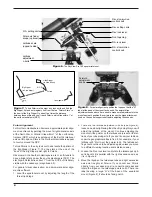
2. Place the base of the equatorial mount onto the tripod

head. Orient the equatorial mount so that the post on the
tripod head lines up between the azimuth adjustment
knobs on the equatorial mount (Figure 2). You may need to
loosen the azimuth adjustment knobs on the equatorial
mount in order to fit the mount into the tripod head.

3. Thread the central support shaft into the equatorial mount

until tight. This will secure the equatorial mount to the tri-
pod head.

4. Remove the knob and washer from the bottom of the cen-

ter support shaft. Slide the tripod support tray up the bot-
tom of the central support shaft until the three tray arms
are touching the legs of the tripod. The flat side of the
accessory tray should be facing up. Make sure the “V” of
each tray arm is against a tripod leg. Place the washer
back on the center support shaft against the tray, and
thread the securing knob all the way up the center support
shaft until it is tight against the tray. The tripod support tray
provides additional stability for the tripod, and holds five
1.25" eyepieces and two 2" eyepieces.

5. Thread the latitude adjustment L-bolt into the rear of the

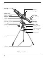
equatorial mount casing as shown in Figure 1.

6. Thread the counterweight shaft into the equatorial mount

at the base of the declination axis until tight. Make sure the
casting at the top of the shaft is threaded clockwise as far
as it will go before attaching the shaft. Once the shaft is
installed, turn the casting counter-clockwise until the top of
the casting is flush with the mount.

7. Remove the knurled “toe saver” retaining screw on the bot-

tom of the counterweight shaft and slide both counter-

weights onto the shaft. Make sure the counterweight lock
knobs are adequately loosened to allow the counterweight
shaft to pass through the hole. Position the counterweights
about halfway up the shaft and tighten the lock knobs.
Replace the toe saver at the end of the bar. The toe saver
prevents the counterweights from falling on your foot if the
lock knobs happen to come loose.

8. Attach the slow-motion control knobs to the right ascen-

sion and declination worm gear shafts of the equatorial
mount by sliding them onto the shafts. Line up the flat on
the end of the shaft with the corresponding feature on the
interior of the knob to attach them properly. The knobs can
be attached to either end of the shafts; use whichever end
is most convenient.

9. Attach the tube rings to the tube ring mounting plate using

the attachment screws that are on the tube rings. The
screws should go through the holes on the outer ends of
the mounting plate and rethread into the tube rings. Note
that the side of the mounting plate with the central “groove”
will be facing up. Use the small wrench to secure the tube
rings to the mounting plate.

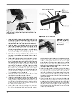
Figure 2. 

Orient the equatorial mount so that the post on the

tripod head lines up between the azimuth adjustment knobs on the
equatorial mount.

4

Post

Azimuth

adjustment

knobs

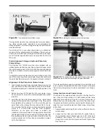
Finder scope

Finder scope bracket

Nylon
alignment
thumbscrews

Focus lock ring

Figure 3b. 

Pull back on

the tensioner and slide the
finder scope into its bracket
until the O-ring is seated in
the bracket ring.

Figure 3a. 

The 6x30 finder scope.

Tensioner

Содержание SkyView Pro 120 EQ 9867

Страница 1: ...roviding Exceptional Consumer Optical Products Since 1975 Customer Support 800 676 1343 E mail support telescope com Corporate Offices 831 763 7000 P O Box 1815 Santa Cruz CA 95061 Orion SkyView Pro 120 EQ 9867 Equatorial Refractor Telescope ...

Страница 2: ...thumbscrew Mounting plate securing knob Counterweight shaft Counterweights Counterweight lock knobs Objective lens Optical tube Tube rings Finder scope Finder scope bracket Eyepiece Star diagonal Focus wheel Right Ascension slow motion control knob Latitude scale Latitude adjustment L bolts Center support shaft Tripod support tray Tripod leg Leg lock knobs ...

Страница 3: ...ar diagonal 1 Finder scope 1 Finder scope bracket with O ring 1 Dust cover 1 Collimation tool 3 Assembly Assembling the telescope for the first time should take about 30 minutes No tools are needed other than the ones provid ed All screws should be tightened securely but be careful not to over tighten or the threads may strip Refer to Figure 1 dur ing the assembly process During assembly and anyti...

Страница 4: ... will go before attaching the shaft Once the shaft is installed turn the casting counter clockwise until the top of the casting is flush with the mount 7 Remove the knurled toe saver retaining screw on the bot tom of the counterweight shaft and slide both counter weights onto the shaft Make sure the counterweight lock knobs are adequately loosened to allow the counterweight shaft to pass through t...

Страница 5: ...cope To ensure smooth movement of the telescope on both axes of the equatorial mount it is imperative that the optical tube is properly balanced We will first balance the telescope with respect to the right ascension R A axis then the declination Dec axis 1 Keeping one hand on the telescope optical tube loosen the R A lock lever Make sure the Dec lock lever is locked for now The telescope should n...

Страница 6: ...scope for proper use To align it first aim the main telescope at an object at least a 1 4 mile away the top of a telephone pole a chimney etc First loosen the R A and Dec lock levers and move the telescope until it is pointing towards the desired object sight along the tube to aim the telescope Turn the focus knob until the object is properly focused Make sure to position the object in the center ...

Страница 7: ... loosened the entire back end of the focuser including any 1 25 diagonal and eyepiece that may be attached comes off exposing the 2 diameter focuser drawtube Now insert your 2 star diagonal into the drawtube and secure with the two thumbscrews loosened previously Insert a 2 eyepiece into the diagonal secure it in place with the thumbscrew on the diagonal and you re ready to observe Note About Chro...

Страница 8: ... to a different viewing location some distance away 3 Loosen the Dec lock lever and rotate the telescope s opti cal tube until it is parallel with the right ascension axis as it is in Figure 6 4 Move the tripod so the telescope tube and right ascension axis point roughly at Polaris If you cannot see Polaris directly from your observing site consult a compass and rotate the tripod so the telescope ...

Страница 9: ...tating the mount about the R A axis You will notice that the object you have previously centered moves in a circular path Use the three alignment setscrews on the polar axis finder to redirect the crosshairs of the polar finder to the apparent center of this circular path Repeat this procedure until the position that the crosshairs point to does not rotate off center when the mount is rotated in R...

Страница 10: ...Figure 9a and thread the entire objective end of the finder inwards or outwards until images appear sharp Re tighten the focus lock ring Once the polar axis finder s objective lens is focused it should not need to be adjusted again Use of the Right Ascension and Declination Slow Motion Control Knobs The right ascension R A and declination Dec slow motion control knobs allow fine adjustment of the ...

Страница 11: ... positive when the telescope is pointing north of the celestial equator Dec 0 and negative when the tele scope is pointing south of the celestial equator Retighten the lock lever Loosen the R A lock lever and rotate the telescope until the right ascension value from the star atlas matches the reading on the R A setting circle Remember to use the lower set of numbers on the R A setting circle Retig...

Страница 12: ... through A good way to judge if the seeing is good or not is to look at bright stars about 40 above the horizon If the stars appear to twinkle the atmosphere is significantly distorting the incom ing light and views at high magnifications will not appear sharp If the stars appear steady and do not twinkle seeing conditions are probably good and higher magnifications will be possible Also seeing co...

Страница 13: ... low magnifications This is because many of them are quite faint yet have some extent apparent width Deep sky objects will often disappear at higher magnifications since greater magnification inherently yields dimmer images This is not the case for all deep sky objects however Many galaxies are quite small yet are somewhat bright so higher power may show more detail The best rule of thumb with eye...

Страница 14: ...cts to appear like the photographs you see in books and magazines most will look like dim gray smudges But as you become more experienced and your observing skills get sharper you will be able to ferret out more and more subtle details and structure How to Find Deep sky Objects Starhopping Starhopping as it is called by astronomers is perhaps the simplest way to hunt down objects to view in the ni...

Страница 15: ...cognition Try exposure times between 1 and 10 seconds depending upon the brightness of the planet to be pho tographed and the ISO of the film being used Piggyback Photography The Moon and planets are interesting targets for the budding astrophotographer but what next Literally thousands of deep sky objects can be captured on film with a type of astrophotography called piggybacking The basic idea i...

Страница 16: ... be necessary If you are unsure or uncomfortable about making optical alignment adjustments we strongly recommend that you just leave it alone Your SkyView Pro 120 EQ comes with a collimating tool Figure 15 shows the collimating tool in place Use of the collimating tool is best done during the day either outdoors or in a well lit room Point the telescope at a dark tar get of uniform brightness lik...

Страница 17: ...ning fluid to a tissue never directly on the optics Wipe the lens gently in a circular motion then remove any excess fluid with a fresh lens tissue Oily fingerprints and smudges may be removed using this method Use caution rubbing too hard may scratch the lens For the objective lens clean only a small area at a time using a fresh lens tissue on each area Never reuse tissues 11 Specifications Objec...

Страница 18: ...18 ...

Страница 19: ...19 ...

Страница 20: ...ay Watsonville CA 95076 If the product is not registered proof of purchase such as a copy of the original invoice is required This warranty does not apply if in Orion s judgment the instrument has been abused mishan dled or modified nor does it apply to normal wear and tear This warranty gives you specific legal rights and you may also have other rights which vary from state to state For further w...

Отзывы: