4
2. Telescope Assembly
Assembly of the Dobsonian Base
Now that you have unpacked the boxes and familiarized your-
self with all the parts in front of you, it’s time to begin assembly.
The optics of the telescope are already installed in the tube, so
most of the required assembly concerns the Dobsonian base.
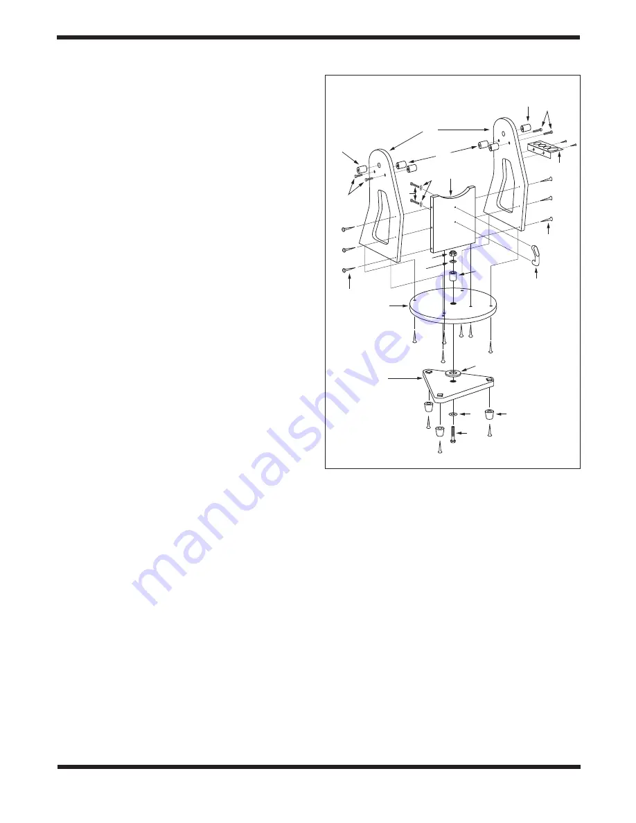
Refer to
Figure 3 during base assembly. The base needs to be
assembled only once, unless you disassemble it for long-term
storage. The assembly takes about 30 minutes and requires a
Phillips screwdriver, two included crescent wrenches, and the
included hex key(s).
Note: When tightening the base assembly screws, tighten
them until firm, but be careful not to strip the holes by
over-tightening. If you use an electric screwdriver, do the
final tightening with a standard screwdriver to avoid strip-
ping.
1. Screw the plastic feet (A) into the underside of the
bottom (triangular) groundplate (B) using the self-tapping
wood screws provided, with a Phillips screwdriver. Insert
the screws through the feet and thread them into the
predrilled starter holes until tight.
2. Loosely attach the front brace (C) to the two side panels
(D) with six of the black base assembly screws (E) in
the predrilled holes. Use the 4mm hex key to tighten
the screws. The side panels should be oriented so the
“SkyQuest XT PLUS” label is facing outward. Do not
completely tighten the screws yet.
3. Line up one of the altitude bearing cylinders (F) with one
of the four bearing cylinder holes on the inside surface
of each side panel. Push a bearing cylinder screw (G)
through the side panel from the outside and thread the
bearing cylinder onto it
. You can tighten the cylinder
by hand or, if needed, with the supplied 4mm hex key.
Repeat for the remaining three bearing cylinders.
4. Attach the side and front panel assembly to the top
groundplate (H) with the remaining six base assembly
screws in the predrilled holes. Tighten all six screws.
5. Tighten the six side panel screws installed earlier.
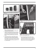
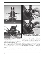
6. Turn the base on its side. Insert the longest (33.75mm)
of the three black plastic bushings (I, see
Figure 4) into
the hole in the center of the top groundplate (H). Push
the bushing in so it goes all the way into the groundplate,
sticking out from the bottom surface (
Figure 5).
7. Now place the white low-friction spacer washer (J) on
the portion of the bushing sticking out from the bottom
(Figure 5).
8. Install the bottom groundplate (B) by lining up its center
hole with the nylon bushing. The white low-friction spacer
washer should now be between the two groundplates
(
Figure 5).
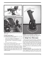
9. Put one metal washer (K) onto the hex head bolt (L), then
insert the bolt through the bushing in the center of the
groundplates from the bottom, as shown in
Figure 3.
10. Now place the remaining metal washer (K) on the bolt,
followed by the lock nut (M). Use the two crescent
wrenches provided to turn the lock nut with one wrench
while holding the hex bolt’s head with the other, or vice
versa (
Figure 6). Tighten the lock nut just enough to allow
a slight separation of the top and bottom groundplates
when the mount is lifted. The purpose of the lock nut
is merely to keep the two groundplates from coming
apart when moving the telescope
.
Over-tightening the
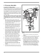
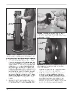
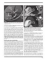
Figure 3.
Exploded view of the XT PLUS Dobsonian base
assembly.
L
K
A
J
B
H
M
K
D
R
R
G
G
E
Q
C
O
F
E
S
N
I
Left
Right


