background image

Safety precautions

9


Assign qualified personnel the task of installing, wiring, operating/controlling, inspecting and 
troubleshooting the product.  
Failure to do so may result in fire, electric shock, injury or damage to equipment.


If this product is used in a vertical application, be sure to provide a measure for the position retention 
of moving parts.  
Failure to do so may result in injury or damage to equipment.


Operate the data setter outside the safety fence. 
Failure to do so may result in injury.


When the driver generates an alarm (any of the driver's protective functions is triggered), take 
measures to hold the moving part in place since the motor stops and loses its holding torque.  
Failure to do so may result in injury or damage to equipment.


Install the products in the enclosure in order to prevent electric shock or injury.


The products are designed with Class I equipment basic insulation. When installing the motor, do not 
touch the product or be sure to ground them.   
Failure to do so may result in electric shock.


Provide an emergency-stop device or emergency-stop circuit external to the equipment so that the 
entire equipment will operate safely in the event of a system failure or malfunction. 
Failure to do so may result in injury.


Perform the return-to-home operation after the power is restored. When an actuator equipped with 
the 

AZ

 Series is used, or when the absolute-position backup system is used in the built-in controller 

type driver with an actuator equipped with the 

AR

 Series, execute positioning operation of the 

absolute mode.  
Failure to do so may result in injury or equipment damage.


Operate the actuator after setting the resolution, moving direction and other parameters. 
If the actuator is operated without setting parameters, the output table may move to unexpected 
directions or run at unexpected speeds, causing injury or damage to equipment. (A variety of 
parameters have been set to the actuator equipped with the 

AZ

 Series at the time of shipment.)


After replacing the driver, set the resolution, moving (rotating) direction or other parameters before 
operating the actuator. 
If the actuator is operated without setting parameters, the output table may move to unexpected 
directions or run at unexpected speeds, causing injury or damage to equipment.


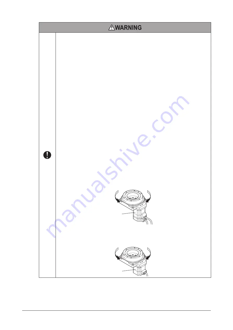
For the actuators equipped with the 

AZ

 Series, the output table rotates in the same direction to the 

CW input (or CCW input) of the driver input signal.

Rotation direction 

when inputting 

the CW signal

Rotation direction

when inputting

the CCW signal

AZ

 Series


For the actuators equipped with the 

AR

 Series or 

RKII 

Series, the output table rotates in the opposite 

direction to the CW input (or CCW input) of the driver input signal. When the CW signal is input, the 
output table rotates in the counterclockwise direction. When the CCW signal is input, the output table 
rotates in the clockwise direction.

AR


Series

RKII

 Series

Rotation direction

when inputting

the CW signal

Rotation direction 

when inputting 

the CCW signal

Содержание DGII Series

Страница 1: ...ndling procedures and safety precautions Please read it thoroughly to ensure safe operation Always keep the manual where it is readily available 1 Introduction 2 2 Safety precautions 8 3 Precautions f...

Страница 2: ...f parameters required when the driver is combined with hollow rotary actuators APPENDIX UL Standards for AZ Series included with products conform to the UL Standards This appendix describes the inform...

Страница 3: ...orm to the UL Standards This does not come with the products without cables 1 4 How to identify the product model Hollow rotary actuator and driver package model z z Actuators equipped with the AZ Ser...

Страница 4: ...VAC S Three phase 200 230 VAC K 24 VDC For DG60 type only 7 Driver type D Built in controller type Blank Pulse input type 8 Reference number 2 Combination with the ARD driver Blank Combination with th...

Страница 5: ...The cable outlet direction represents the cable direction when the output table is faced to the near side and the motor is placed to the down side L Cable is drawn to the left side Blank Cable is draw...

Страница 6: ...1 5 Names of parts DGM60 Positioning pin holes 2 places It can be used as a mounting holes if positioning is not performed Motor cable Motor Motor Motor encoder connector Motor encoder lead wires Enc...

Страница 7: ...places Electromagnetic brake cable Motor cable Motor Electromagnetic brake Home sensor mounting bracket fixed screw holes 2 places Gear reduction mechanism Shielded plate fixed screw holes 2 places En...

Страница 8: ...product without observing the instructions that accompany a CAUTION symbol may result in bodily injury or property damage These notes appear throughout the manual and describe items that must be obser...

Страница 9: ...ckup system is used in the built in controller type driver with an actuator equipped with the AR Series execute positioning operation of the absolute mode Failure to do so may result in injury or equi...

Страница 10: ...njury Do not touch the terminals while conducting the insulation resistance measurement or dielectric strength test Doing so may cause electric shock Do not use the home sensor set accessory as safety...

Страница 11: ...an encoder ABZO sensor may cause the motor malfunction or damage to the encoder ABZO sensor When transporting the actuator or installing a load handle the actuator carefully not to make a strong impa...

Страница 12: ...ack shaft of the motor z z Hollow hole section If the pipe or cable installed in the hollow hole section is rotated together with the output table take measures not to rub or disconnect in contact wit...

Страница 13: ...th holding the cable lead wires may result in damage to the connector z z Bending radius of cable Use the cable in a state where the bending radius of the cable is more than six times of the cable dia...

Страница 14: ...subject to splashing water rain water droplets oil oil droplets or other liquids Area free of excessive salt Area not subject to continuous vibration or excessive shocks Area free of excessive electr...

Страница 15: ...lar inspections Alternatively install an oil pan or other device to prevent leakage from causing further damage Oil leakage may lead to problems in the user s equipment or products Do not loosen or re...

Страница 16: ...tion method of DGM60 type Position the actuator using two positioning pin holes and secure the mounting holes with screws two pieces Provide screw hole machining in the mounting plate since the mounti...

Страница 17: ...ashers Positioning pin holes 2 places Use as mounting holes Mounting holes 2 places Pilot receiving hole Pilot When a mounting plate with through hole is used z z Design for mounting plate reference u...

Страница 18: ...el Thickness Material DGM85 8 mm 0 31 in or more Steel or aluminum DGM130 10 mm 0 39 in or more DGM200 15 mm 0 59 in or more z z Specifications for mounting hole and positioning pin hole Model Mountin...

Страница 19: ...s 2 places Screw hole machining in a mounting plate Be sure to install the actuator from the upper side of the mounting plate It cannot be installed from below the mounting plate When a mounting plate...

Страница 20: ...72 110 4 33 72 2 83 110 4 33 90 3 54 65 2 56 13 0 51 4 M8 R36 1 42 90 3 54 150 0 1 5 906 0 004 A 6 0 24 Details of section A 2 1 5 deep 5 0 012 0 0 1969 deep 0 20 0 0005 0 5 d e e p 5 0 0 1 2 0 0 1 9...

Страница 21: ...actuator which cable outlet direction is downward The figure shows the DGM130R AZAC Be sure to install the actuator from the upper side of the mounting plate It cannot be installed from below the moun...

Страница 22: ...is rightward or leftward This section explains based on an example when the cable outlet direction is rightward The figure shows the DGM130R AZACR Be sure to install the actuator from the upper side...

Страница 23: ...Deep groove ball bearing M3 1 N m 142 oz in 8 mm 0 31 in Steel or aluminum DGM85 Deep groove ball bearing M4 2 N m 280 oz in 6 mm 0 24 in DGM85R Cross roller bearing 8 mm 0 31 in DGM130 Deep groove b...

Страница 24: ...F is applied at distance L from the center of the output table F N L m Load mass m kg mg Fulcrum Load moment M N m Load moment N m M F L Axial load N Fs F m load mass g gravitational acceleration z z...

Страница 25: ...procedure 100 120 VAC 200 240 VAC 24 VDC 48 VDC 1 Protective Earth Terminal of the driver Required to ground Required to ground Required to ground 2 Grounding wire of the motor Required to ground Not...

Страница 26: ...power input type is not required Grounding wire AWG18 0 75 mm2 or more Screw size of Protective Earth Terminal M4 Tightening torque 1 2 N m 170 oz in Grounding Protective Earth Terminal 5 3 Connectio...

Страница 27: ...or can be installed to either of the screw holes right or left Install it to the position in which an indicating light can be seen DGM60 DGM85 DGM130 DGM200 Screws M3 Sensor Sensor mounting bracket Sc...

Страница 28: ...nsor is designed for use inside equipment and therefore has no special means of protection against disturbance light If the actuator is to be used under an incandescent lamp or in conditions that are...

Страница 29: ...od When the pink color lead is connected to the brown color lead the sensor logic will be normally closed Connection example for the home sensor set PADG SBY PNP type The connection example is shown b...

Страница 30: ...x months thereafter As needed During inspection Check if any of the screws having installed the actuator comes loose Check if any of the screws having installed a load comes loose Check if a damage or...

Страница 31: ...ith the driver Refer to the OPERATING MANUAL Driver for details RoHS Directive The products do not contain the substances exceeding the restriction values of RoHS Directive 2011 65 EU 7 2 Specificatio...

Страница 32: ...0 to 40 C 32 to 104 F Non freezing Actuators equipped with the AR Series RKII Series When the home sensor is not used 0 to 50 C 32 to 122 F Non freezing When the home sensor is used 0 to 40 C 32 to 10...

Страница 33: ...C 6 4 A or more 0 25 A or more 0 5 A or more DGM200R AZ C DG85R AZ CD DGM85R AZ C AZD CD Single phase Three phase 200 240 V 15 to 6 Single phase 1 7 A or more Three phase 1 0 A or more 0 25 A or more...

Страница 34: ...t type z z Built in controller type Model Actuator model Driver Control power supply 24 VDC 5 Driver model Power supply input voltage Frequency Power supply current capacity DG85R AR AD DGM85R AR C AR...

Страница 35: ...or more 0 75 A or more DG85R AR S DGM85R AR C ARD S LSD S Three phase 200 230 V 15 to 10 1 0 A or more 0 5 A or more DG130R AR S DGM130R AR C 1 4 A or more 0 5 A or more 0 75 A or more DG200R AR S DG...

Страница 36: ...0 60 Hz 1 9 A or more DG130 RKSAA DGM130 5PKEAC RKSD507 A 3 8 A or more DG85 RKSAC DGM85 5PKEAC RKSD503 C Single phase 200 240 V 15 to 10 1 2 A or more DG130 RKSAC DGM130 5PKEAC RKSD507 C 2 4 A or mor...

Страница 37: ...name Actuator model Standard With electromagnetic brake MDG60B DGM60 MDG85A2 DGM85 MDG85B2 MDG130A2 DGM130 MDG130B2 MDG200A DGM200 MDG200B The cable outlet direction is downward only z z Equipped with...

Страница 38: ...38...

Страница 39: ...39...

Страница 40: ...The third party products mentioned in this manual are recommended products and references to their names shall not be construed as any form of performance guarantee Oriental Motor is not liable whats...

Отзывы: